Movable sludge material conveying box

A technology of mobile conveying and sludge, applied in conveyors, mechanical conveyors, transportation and packaging, etc., can solve the problems of strong water-holding adhesion of sludge, reduced conveying efficiency, inability to unload by itself, etc., to achieve a convenient high-altitude state The effect of automatic unloading, automatic and smooth opening and closing, reliable and safe loading and unloading of materials

Pending Publication Date: 2019-03-26
HUNAN HENGKAI ENVIRONMENT TECH INVESTMENT CO LTD
View PDF0 Cites 3 Cited by
  • Summary
  • Abstract
  • Description
  • Claims
  • Application Information

AI Technical Summary

Problems solved by technology

In the process of sludge treatment process, various sludge materials (conditioning mixed sludge, fermentation sludge, etc.) need to be transported in a large amount in a centralized manner, because sludge has strong water holding capacity, strong cohesiveness, and poor fluidity. There will be problems such as wall sticking, accumulation, hardening, and incomplete discharge in the conveying cavity.
[0003] Such as ordinary screw conveying equipment, the sludge is easy to stick or agglomerate on the screw blade, rotating shaft, and discharge port, resulting in a smaller cavity volume and lower conveying efficiency. In severe cases, the rotating shaft and blade may be stuck, and the drive motor may be burned.
[0004] For example, in conventional bucket elevators and discharge hopper equipment, the sludge is easy to stick or agglomerate on the wall of the hopper or the discharge hopper of the hopper, resulting in blockage of material conveying, difficult discharge, incomplete discharge, and reduced conveying volume. Small and other situations
[0005] The manual operation of the hook for hoisting the conventional material box, the manual cooperation to open the material door is labor-intensive and dangerous
[0006] The above-mentioned conventional equipment is used for material transportation, and at the same time, there are small transportation volume, low reloading capacity, low production efficiency, and material falling during transportation affects the sanitation of the working environment, etc.
[0007] Conventional belt conveyors can be used to transport materials quickly, and a single grab crane can also grab and reload materials, but these devices cannot guarantee that materials will be spilled during movement, and the dust and odor will be strong; at the same time, they want to process multiple materials in a short time For grabbing and transferring, multiple grab cranes or belt conveyors need to be equipped in the work area, which is not ideal for space and economy
[0008] To sum up, due to the bonding characteristics of sludge, the existing sludge transportation and unloading equipment has small conveying capacity, low production efficiency, incomplete unloading, difficult manual removal, large operational safety hazards, high risk, and high labor intensity. , Unable to self-unloading, unsatisfactory space and economy, etc., these will directly affect the stable operation of the subsequent sludge treatment process

Method used


Image

  • Movable sludge material conveying box
  • Movable sludge material conveying box
  • Movable sludge material conveying box

Examples


Embodiment 1

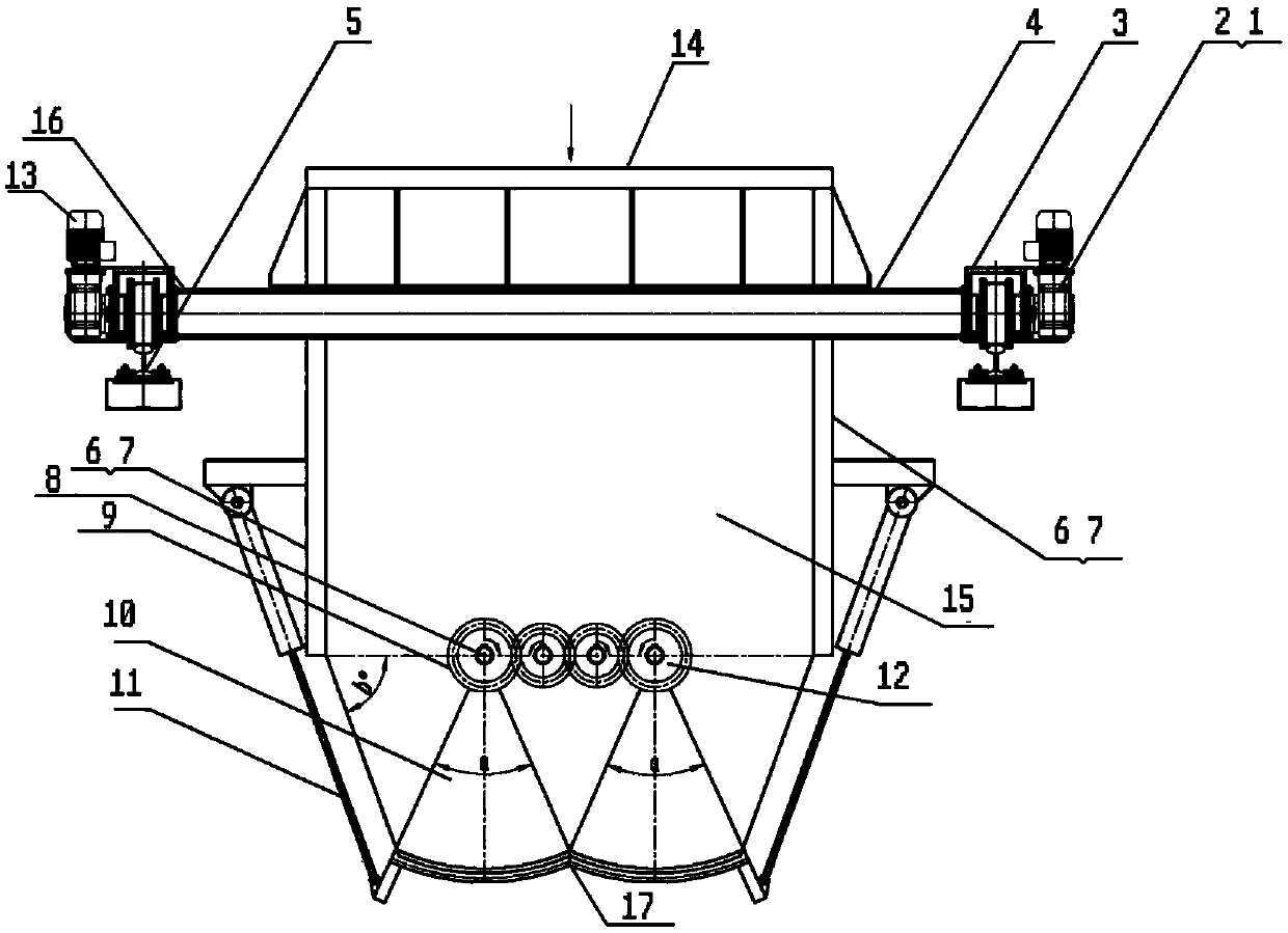
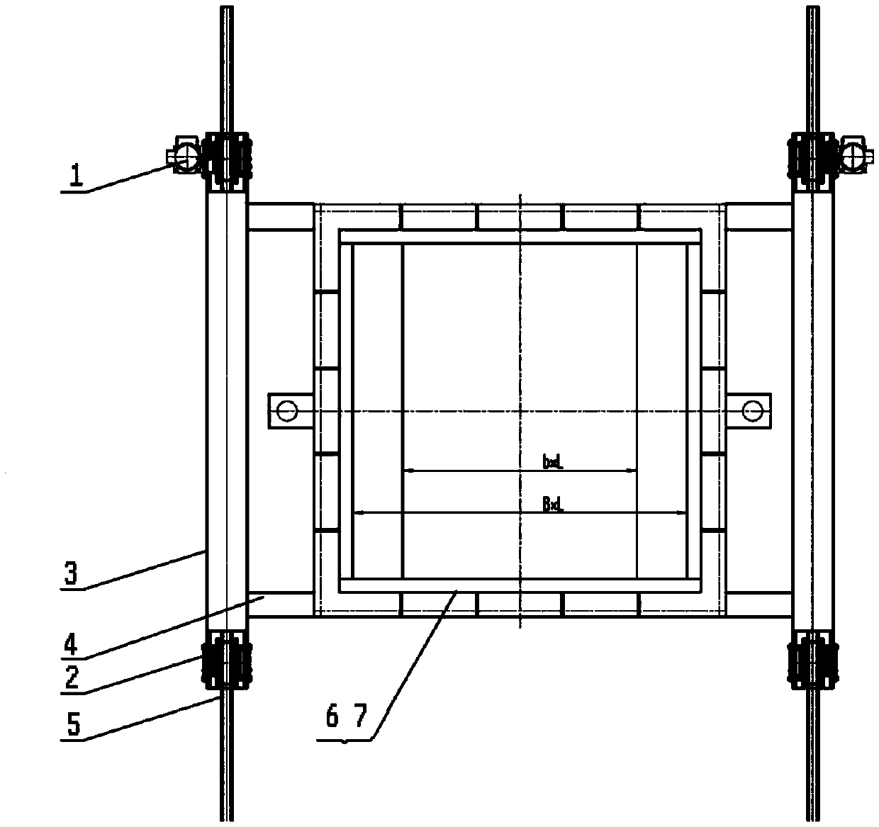
[0055] Such as Figure 1-2 As shown, a kind of mobile conveying sludge hopper in this implementation includes steel rail 5, steel beam mobile trolley 16, sludge self-discharging hopper 15 and electric control (not shown). There are two steel rails 5, which are parallel and suspended between the starting point and the end point of the material. The steel girder mobile trolley 16 includes a pair of driving wheel sets 1, a pair of driven wheel sets 2, two end beams 3, and a shaped steel frame beam platform 4. A pair of driving wheel sets 1 are driven by a motor and a reducer as a driving power source 13. The driving wheel set 1 and the driven wheel set 2 are assembled and connected through the end beam 3, and the driven wheel set 2 is preferentially arranged in front of the material transportation direction. The end beams 3 and the rails 5 are located on both sides correspondingly. The shaped steel frame beam platform 4 is a rectangular frame structure platform composed of two h...

Embodiment 2

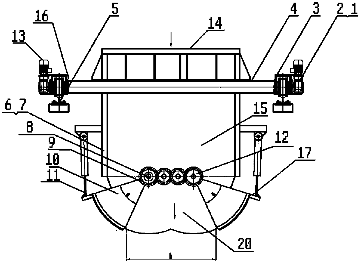
[0064] Such as Figure 5-6 As shown, a mobile conveying sludge hopper in this embodiment includes a steel rail 5, a steel beam mobile trolley 16, a sludge self-discharging hopper 15 and an electric control (not shown). There are two steel rails 5, which are parallel and suspended between the starting point and the end point of the material. The steel beam mobile trolley 16 includes a pair of driving wheel sets 1, a pair of driven wheel sets 2, two end beams 3, and a shaped steel frame beam platform 4. The shaped steel frame beam platform 4 is composed of two horizontal beams and two vertical beams. A rectangular frame structure platform is formed, the upper surface is a flange surface structure, and a pair of driving wheel sets 1 are driven by a motor and a reducer as a driving power source 13. The driving wheel set 1 and the driven wheel set 2 are located on the end beam 3, through The end beams 3 are assembled and connected, and the driven wheel set 2 is preferentially arra...

Embodiment 3

[0072] Such as Figure 10 As shown, a mobile sludge transporting bin in this embodiment has a larger volume transporting function. According to the conveying height, distance, space and process requirements, it can be carried out in the form of two bin trolleys with bin A+ bin B sharing the same track. Material transport, simultaneous or staged discharge.

[0073] It is also possible to adopt multiple groups of material boxes in the same steel beam mobile trolley 15 to arrange transportation and unload in stages.


PUM


Abstract

The invention provides a movable sludge material conveying box. The movable sludge material conveying box comprises rails, a material trolley, a sludge self-discharging material box and an electroniccontroller, wherein the rails are two parallel suspended steel rails; the material trolley comprises a driving device, a driven wheel set and a driving wheel set; the sludge self-discharging materialbox is fixed on the material trolley, an open feeding port is arranged at the top, discharging doors which are opened oppositely are arranged at the bottom, and a box body is symmetrically distributedwith respect to the rails on the two sides; a discharging door unit comprises a pair of the symmetrically distributed discharging doors and a reciprocating mechanism connected with the discharging doors, and the discharging doors synchronously move to two sides to be opened or synchronously move oppositely to be closed; and the electronic controller is connected with the driving device and the reciprocating mechanism, controls the material trolley to walk or stand still on the rails and controls opening and closing of the discharging doors. The movable sludge material conveying box has a large-volume conveying function, achieves material reciprocating conveying according to the line distance between the conveying starting point and the final point and achieves automatic running and operation. The discharging doors are closed and opened automatically, and discharging is thorough.

Description

technical field [0001] The invention belongs to the technical field of material conveying and unloading, and in particular relates to a mobile conveying sludge hopper. Background technique [0002] As the scale of cities and towns continues to expand, the water consumption for urban living and production continues to increase, and the generation of urban sewage has increased sharply. Urban sewage treatment produces a large amount of sludge containing odor, pathogenic bacteria and heavy metals every day. These sludge will be accumulated and landfilled in subsequent land It will occupy a large amount of land and pollute the ecological environment again. At present, the moisture content of the sludge produced by urban sewage plants is basically about 80%. Through the treatment technologies such as aerobic fermentation and dry incineration of sludge, the reduction, harmlessness and stabilization of sludge can be better realized. In the process of sludge treatment process, vario...

Claims


Application Information

Patent Timeline
Patent Type & Authority Applications(China)
IPC IPC(8): B65G35/00B65G65/40
CPCB65G35/00B65G65/40B65G2201/0235
Inventor 罗志诚秦国春
Owner HUNAN HENGKAI ENVIRONMENT TECH INVESTMENT CO LTD
Why Eureka
Try Eureka