Positioning fixture for welding shielding ring and insert

A positioning tooling and insert positioning technology, applied in welding equipment, auxiliary welding equipment, welding/cutting auxiliary equipment, etc., can solve the problems of inaccurate positioning, decreased production efficiency, low product yield, etc. The effect of stable compaction, ensuring positioning accuracy and positioning reliability

Active Publication Date: 2019-05-21
STATE GRID CORP OF CHINA +1
View PDF7 Cites 6 Cited by
  • Summary
  • Abstract
  • Description
  • Claims
  • Application Information

AI Technical Summary

Problems solved by technology

[0004] However, when the above-mentioned welding tool is applied to the welding positioning process of the shielding ring and the insert, since the cross section of the shielding ring is circular, in the process of positioning the shielding ring, the positioning between the positioning groove and the shielding ring is Line contact positioning, which will cause the shielding ring to be deflected in the circumferential direction during the positioning process, and the positioning will be inaccurate, which will lead to the inability of the axis of the insert to be accurately aligned with the center circle of the shielding ring section, resulting in the welding process in the later stage. The welding positioning accuracy of each insert is inconsistent, the finished product rate of welding and forming products is low, and the production efficiency is reduced

Method used


Image

  • Positioning fixture for welding shielding ring and insert
  • Positioning fixture for welding shielding ring and insert
  • Positioning fixture for welding shielding ring and insert

Examples


Embodiment Construction

[0028] Embodiments of the present invention will be further described below in conjunction with the accompanying drawings.

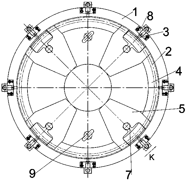
[0029] The specific embodiment of the positioning tool for shielding ring and insert welding of the present invention, as figure 1 As shown, the positioning tool includes a base plate 1, which is a circular plate and has a central axis extending in the up-down direction. In this embodiment, the plane where the upper surface of the base plate 1 is located is set as the reference plane, and the reference plane is set for It can unify the positioning and installation datum of each component, ensure the unification of the datum and then ensure the accuracy of the positioning of the overall structure.

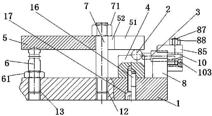
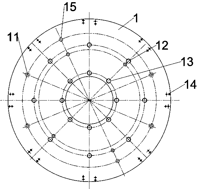
[0030] like figure 1 , figure 2 and image 3 As shown, the upper plate surface of the bottom plate 1 is located at the middle position in the radial direction and is provided with a positioning ring 4. The positioning ring 4 is circular, and positioning pi...


PUM


Abstract

The invention relates to a positioning fixture for welding a shielding ring and an insert. The positioning fixture for welding the shielding ring and the insert comprises a supporting seat with a central axis and an insert positioning seat; the positioning fixture is provided with a set datum plane which is perpendicular to the central axis; a positioning groove which is used for placing the shielding ring is formed in the supporting seat; the positioning groove is provided with a positioning groove wall and a notch; the centre circle of the cross section of the shielding ring at a set position is perpendicular to the central axis; the centre of the centre circle of the cross section is positioned in the central axis; a set distance is reserved between the centre circle of the cross section and the datum plane; more than two pressing plate components are uniformly distributed in the circumferential direction around the central axis of the supporting seat at intervals; each pressing plate component comprises a pressing plate, a compressing mechanism and a stop positioning piece; a contact position between the shielding ring and each pressing plate is taken as a supporting point; anda reverse torque is respectively applied to each pressing plate by the corresponding compressing mechanism and the corresponding stop positioning piece. The positioning precision and the positioningreliability between the shielding ring and the insert are ensured.

Description

technical field [0001] The invention relates to a positioning tool for welding a shielding ring and an insert. Background technique [0002] The Chinese invention patent application document with the application publication number CN108320869A discloses a DC pot insulator. The pot insulator includes a shielding ring and an insert (that is, an insert) arranged outside the shielding ring. The shielding ring is arranged on the epoxy In the aluminum oxide composite part, it is connected with the outer flange through the insert. The axial section of the shielding ring is circular, the radial section is circular, and the center line of each circular surface of the axial section of the circular ring forms a section center circle, and the center of the section center circle is located at On the axis of the shielding ring; there are multiple inserts, arranged at intervals around the axial direction of the shielding ring, and the inserts are cylindrical, the axis of the inserts is ar...

Claims


Application Information

Patent Timeline
Patent Type & Authority Applications(China)
IPC IPC(8): B23K37/04
Inventor 鲁小荣徐亦琛王晶张力方张跃王旭辉张盼
Owner STATE GRID CORP OF CHINA
Why Eureka
Try Eureka