Industrial robot collision preventing method

A technology for industrial machines and robots, applied in manipulators, manufacturing tools, program-controlled manipulators, etc., can solve the problems of increased complexity of detection algorithms and increased time complexity of collision detection algorithms, so as to reduce the calculation amount of intersection detection and avoid collisions. , the program is simple effect

Inactive Publication Date: 2019-05-21
NANJING ESTUN ROBOTICS CO LTD
View PDF7 Cites 12 Cited by
  • Summary
  • Abstract
  • Description
  • Claims
  • Application Information

AI Technical Summary

Problems solved by technology

The object model proposed in this method is an arbitrary polyhedron. In the actual complex production environment, this object model will increase the time complexity of the collision detection algorithm of a single node, and it is necessary to detect all moving objects and all other objects in each cycle. Whether the object collides, the complexity of the detection algorithm increases

Method used


Image

  • Industrial robot collision preventing method
  • Industrial robot collision preventing method
  • Industrial robot collision preventing method

Examples


Embodiment approach 1

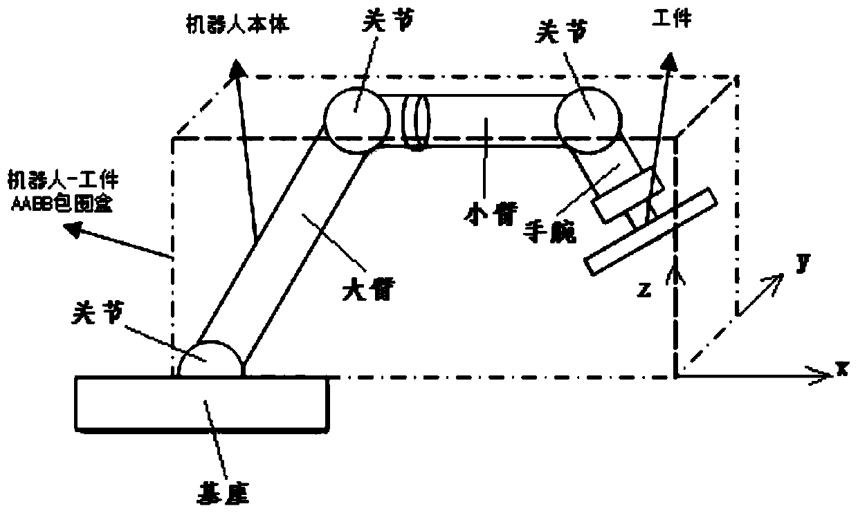
[0044]Embodiment 1 is a method for detecting whether the industrial robot collides with the clamped workpiece or external tooling when an industrial robot consisting of a base, a large arm, a small arm, and a wrist moves to clamp a workpiece.

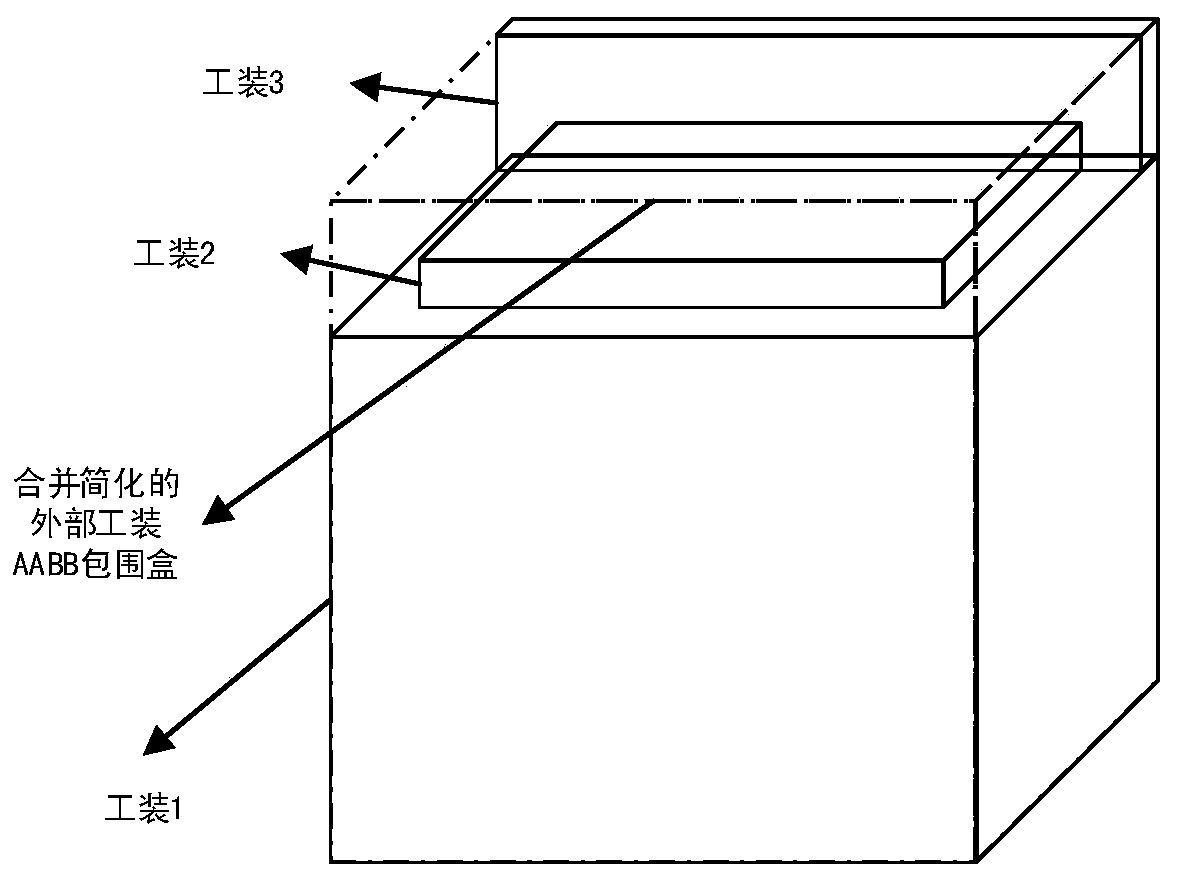
[0045] Assume that the current calculation time of the movement of the workpiece clamped by the robot is t=50ms, and the control calculation period is 10ms; there are three external toolings, namely external tooling 1, external tooling 2 and external tooling 3.

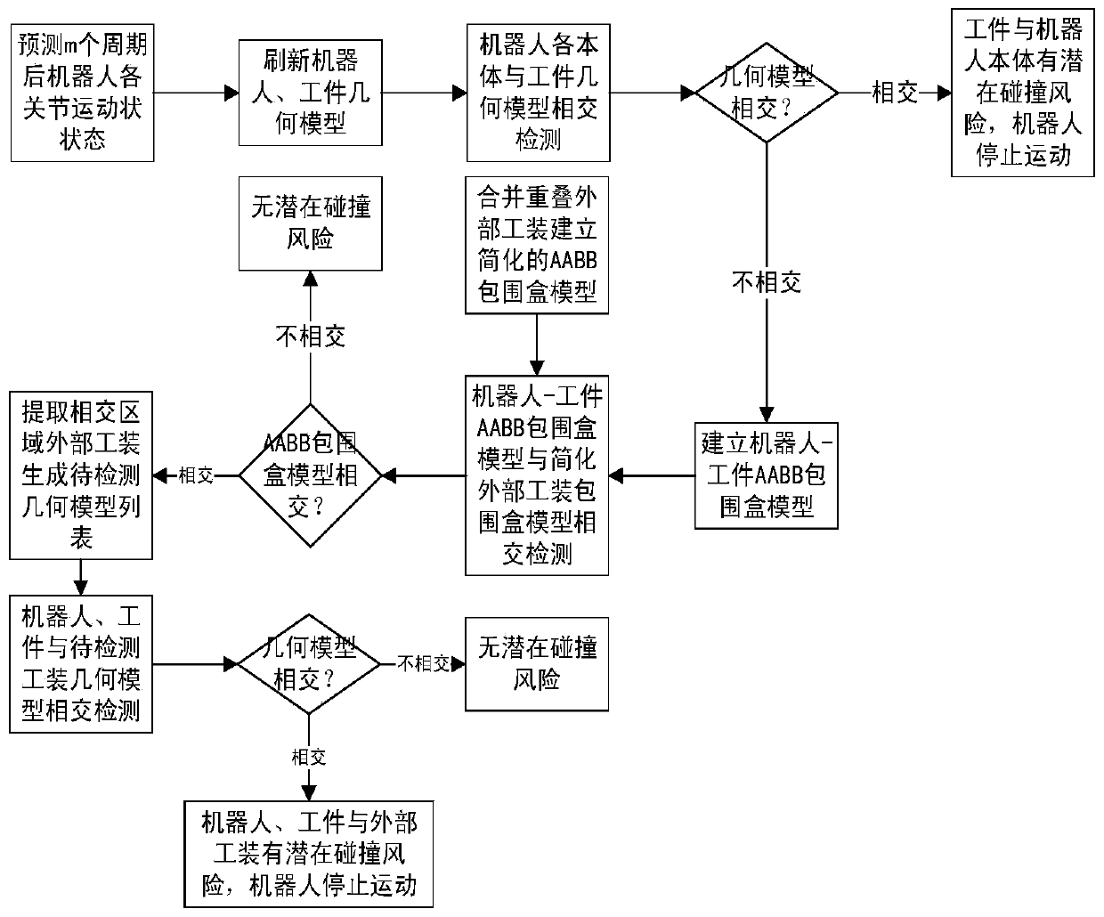
[0046] refer to figure 1 , the robot anti-collision method of Embodiment 1 includes the following steps connected in sequence:

[0047] Step 1.1, establish the geometric model of the robot, the workpiece geometric model and the external tooling geometric model in the initial state;

[0048] The geometric model of the robot and the workpiece is a geometric model defined by the mechanical properties of the robot and the workpiece, that is, a set of three-dimensional graphics com...

Embodiment approach 2

[0081] The method of embodiment 2 is basically the same as that of embodiment 1, the only difference is that the compensation period parameter γ is introduced in the method of confirming the forecast period m, m=t stop / Δt+γ; where γ is the compensation period parameter.

[0082] In this embodiment, assuming that the compensation cycle parameter γ is 1, the calculation method of the cycle m is m=10 / 2+1=6. The number of m cycles in Embodiment 2 is 6, and compared with Embodiment 1, the number of m cycles is increased by one. That is to say, in Embodiment 2, at the current moment, it is possible to predict whether a potential collision occurs at the time t=50+6*10=110ms, while in Embodiment 1, it is only possible to predict whether a potential collision occurs at the time t=50+5*10=100ms . That is to say, the method in Embodiment 2 can predict the risk of collision earlier than Embodiment 1, provide more sufficient stopping time, and a longer stopping distance.

[0083] Accor...


PUM


Abstract

The invention discloses an industrial robot collision preventing method. Firstly, geometric models of a robot and a workpiece are refreshed according to the predicted robot motion state, and robot andworkpiece geometric model crossed detection is conducted, and accordingly whether the risk that the workpiece collides with a robot body exists or not is detected; after it is detected that the robotand the workpiece are free of the collision risk, an AABB surrounding box model is established according to the refreshed robot and workpiece geometric models, accordingly, workpiece AABB surroundingbox model crossed detection is simplified, finally, the robot, the workpiece and outer tools in the crossed area are subjected to crossed detection, tools not in the crossed area do not need to be subjected to crossed detection, and accordingly the crossed detection operand is reduced. The procedure is simple, and the execution efficiency is high. By means of the method, the collision risk can bedetected in time before potential collisions happen, the robot is stopped, collisions are avoided, and the method is suitable for any running work condition of the robot.

Description

technical field [0001] The invention relates to industrial robots, in particular to an anti-collision method for industrial robots. Background technique [0002] During the movement of the industrial robot, due to various reasons, the robot body and the fixture, the robot and the external tooling or personnel will collide, resulting in damage or damage to the robot body, the workpiece and the external tooling. Therefore, how to detect and avoid collisions is very important in robot applications. [0003] The existing collision detection methods mainly include offline simulation based on path planning and real-time detection based on torque feedback. The offline detection method often requires a lot of computing resources; the robot running program needs to be written in advance; and because it is only for the pre-configured workspace, the collision model cannot be corrected according to the change of the real-time working conditions, and the robot cannot jog and follow. Co...

Claims


Application Information

Patent Timeline
IPC IPC(8): B25J9/16B25J19/06
CPCB25J9/16B25J19/06
Inventor 吴俣王继虎夏正仙冯日月潘婷婷王杰高
Owner NANJING ESTUN ROBOTICS CO LTD
Why Eureka
Try Eureka