
A valve guide and its manufacturing method

A valve guide and manufacturing method technology, which is applied to lift valves, mechanical equipment, valve devices, etc., can solve the problems of difficult valve guide processing, increased valve guide wear, and increased oil consumption, so as to avoid emission of particulate pollutants, The effect of reducing frictional work and optimizing emission performance

Active Publication Date: 2017-01-18
WEICHAI POWER CO LTD
View PDF6 Cites 0 Cited by
  • Summary
  • Abstract
  • Description
  • Claims
  • Application Information

AI Technical Summary

Problems solved by technology

However, due to the limitation of its own structure, the contact area between the valve stem and the valve guide is reduced, which will easily cause the wear of the valve guide to increase, and the gap between the valve guide and the valve stem will increase, causing more oil to penetrate into the combustion chamber and eventually increase the oil consumption. , resulting in worsening emissions
In addition, valve guides with annular grooves are more difficult to process

Method used


Image

  • A valve guide and its manufacturing method
  • A valve guide and its manufacturing method
  • A valve guide and its manufacturing method

Examples


Embodiment 1

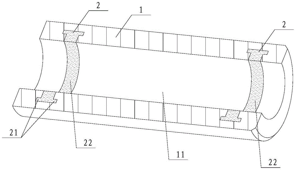
[0036] See figure 1 , this figure is a schematic diagram of the overall structure of the valve guide described in the first embodiment. In order to clearly show the core design of this solution, this figure is an axial section of the inspection tool for measuring the height of the cone surface of the valve seat ring described in this embodiment. Schematic diagram of the working state, which is expressed in the form of axial section.

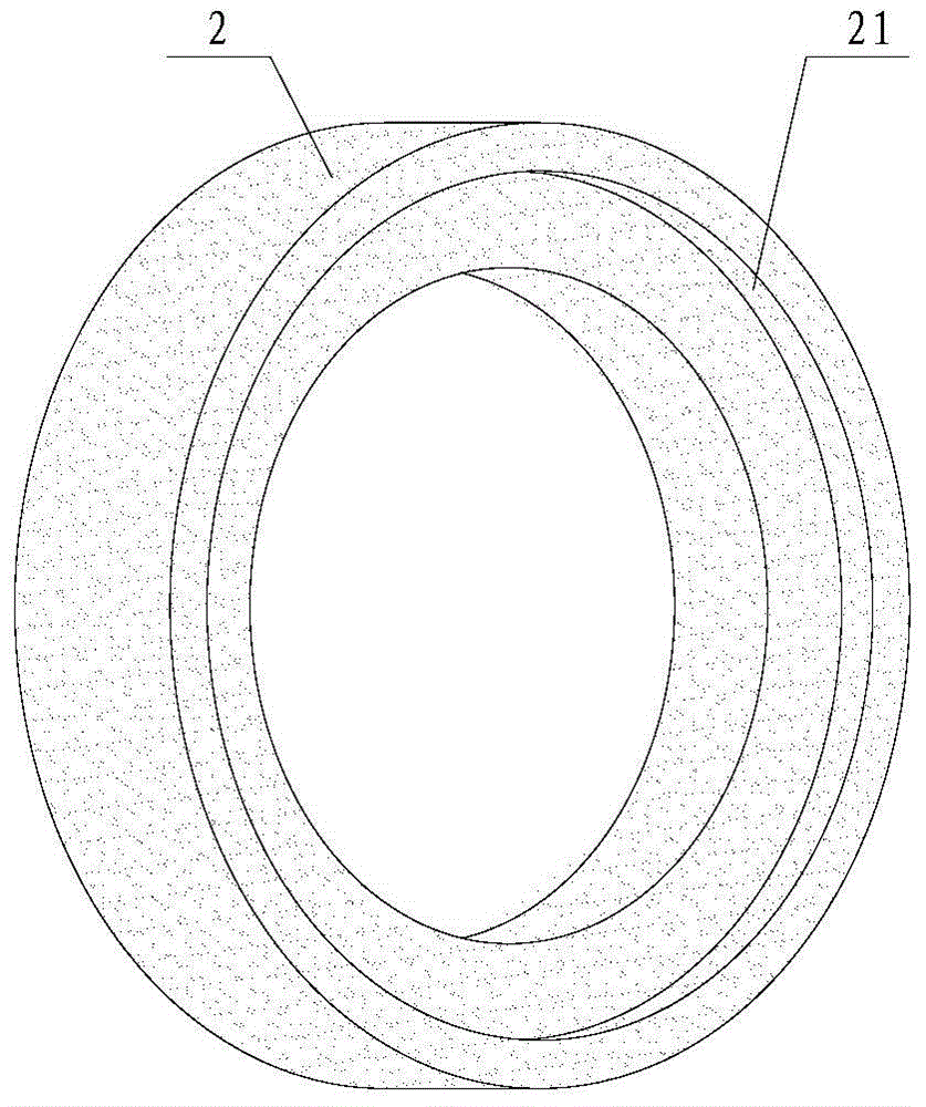
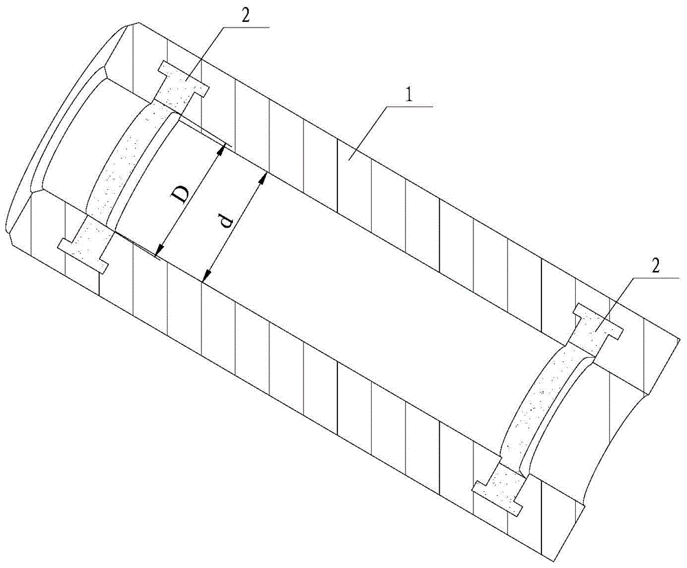
[0037] The valve guide is composed of two main parts: the valve guide body 1 and the porous high-temperature resistant insert 2 embedded in the inner wall of the valve guide body 1, and the porous high-temperature resistant insert 2 is formed with the valve guide body 1 and the valve stem (Fig. not shown in ) the internal cylindrical surface of the clearance fit; that is to say, the inner peripheral surface 22 of the porous high temperature resistant insert 2 is the same diameter as the inner peripheral surface 11 of the valve guide body 1, and t...

Embodiment 2

[0051] See Figure 4 , which is a schematic axial cross-sectional view of the porous high-temperature resistant insert shown in the second embodiment.

[0052] Compared with the first embodiment, the porous high-temperature resistant insert 2' of this solution is also annular, the only difference is that the porous high-temperature resistant insert 2' of this solution is made of silicon nitride porous ceramic material , the limiting part 21' adopts a different structure, such as Figure 4 As shown, in its axial section, the limiting portion 21 ′ is formed by extending from both axial sides of the body of the porous high-temperature resistant insert 2 ′, and is generally triangular in shape.

Embodiment 3

[0054] See Figure 5 , which is a schematic axial cross-sectional view of the porous high-temperature resistant insert shown in the third embodiment.

[0055] Compared with the first and second embodiments, the porous high-temperature resistant insert 2" described in this solution is also annular, the only difference is that the porous high-temperature resistant insert 2" described in this solution is made of alumina porous ceramics , the number of setting of the limit part 21" is different. For example Figure 5 As shown, in its axial section, the limiting portion 21" protrudes from two bosses on both axial sides of the body of the porous high-temperature resistant insert 2".

[0056] Same as the first embodiment, the porous high-temperature resistant inserts in the second and third embodiments can also be pre-embedded in the casting sand mold of the valve guide, cast and solidified by molten iron. I won't repeat them here.

[0057] In addition, it should be noted that, in...


PUM

PropertyMeasurementUnit
melting pointaaaaaaaaaa

Abstract

The invention discloses a valve guide pipe matched with a valve rod. The valve guide pipe comprises a valve guide pipe body and a porous high temperature resistant insert which is inserted into the inner wall of the valve guide pipe body. The porous high temperature resistant insert and the valve guide pipe body form an inner cylindrical surface matched with the valve rod in a clearance mode. A large amount of machine oil can be stored in air holes of the porous high temperature resistant insert, the porous high temperature resistant insert can move up and down in a reciprocating mode along with a valve in the using process, the machine oil can form an appropriate oil film between the valve rod and the valve guide pipe body, and therefore the lubrication performance is guaranteed; in addition, the machine oil can be prevented from leaking into a combustion chamber due to the oil film, consumption of the machine oil is reduced, and the discharge performance of the complete machine is optimized. In addition, the porous high temperature resistant insert has the high temperature resistance, the porous high temperature resistant insert can be pre-buried into a casting sand mold and reliably inserted into the valve guide pipe body through iron liquid casting and solidification, and the good machining technology is achieved. Based on the valve guide pipe, the invention further provides a manufacturing method of the valve guide pipe.

Description

technical field [0001] The invention relates to the technical field of engine component processing, in particular to a valve guide and a manufacturing method thereof. Background technique [0002] As we all know, the gas distribution mechanism is one of the important components of the engine. During the working process, the main function of the gas distribution mechanism is to automatically open and close the intake and exhaust valves of each cylinder according to a certain time limit. Its function is to supply combustible mixture gas (gasoline engine) or fresh air (diesel engine) to the cylinder through the air intake valve in time, and discharge the waste gas formed after combustion and work from the exhaust valve in time to realize the ventilation and replenishment of the engine cylinder. the whole process. [0003] Among them, the valve stem reciprocates in a straight line in the valve guide, and the lubricating oil splashed from the valve mechanism is used to lubricate...

Claims


Application Information

Patent Timeline
Patent Type & Authority Patents(China)
IPC IPC(8): F01L3/08B22D19/00
Inventor 关慧欢张春波李涛张怀青
Owner WEICHAI POWER CO LTD
Learn More