

Fixture
A technology of a fixture and a magnetic field generating device, which is applied in the field of medical devices and can solve problems such as device deformation or damage
- Summary
- Abstract
- Description
- Claims
- Application Information
AI Technical Summary
Problems solved by technology
Method used
Image

Examples
Embodiment 1
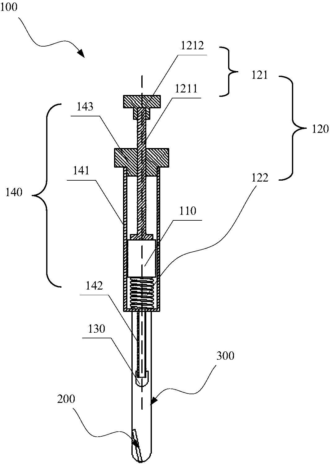
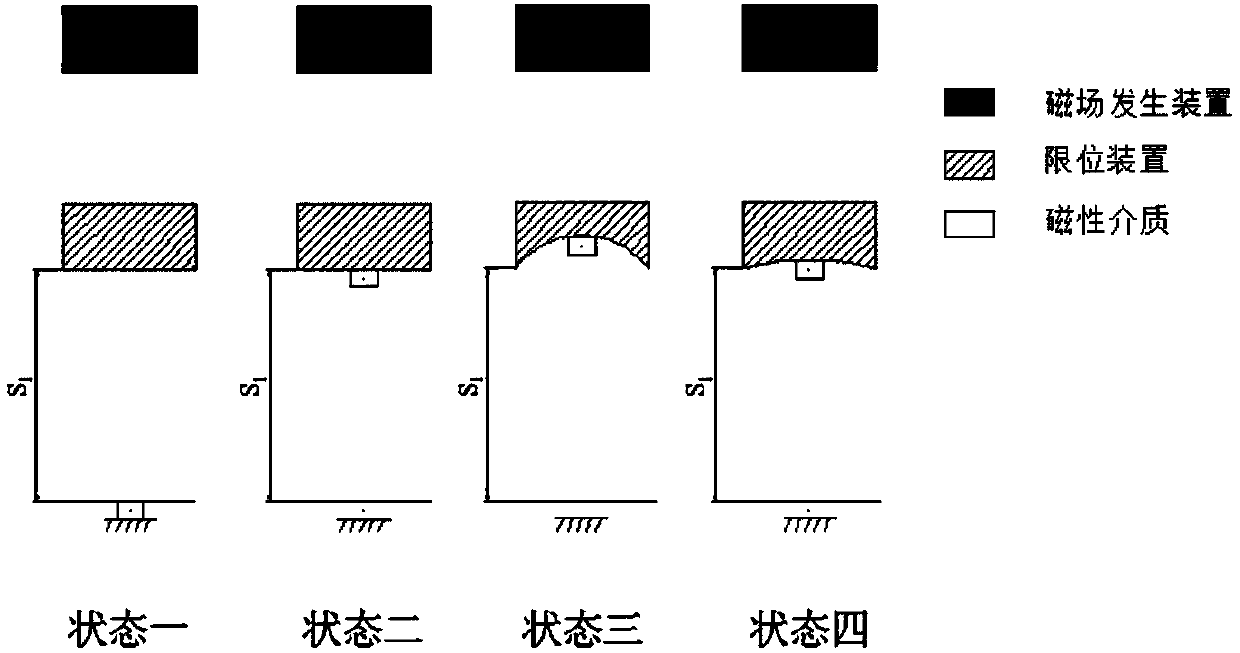
[0034] Please refer to figure 1 , the present embodiment provides a jig 100 that can be used to transfer magnetic objects, and is especially suitable for positioning and transferring light and small magnetic media that are easily deformed by force. The fixture 100 includes a magnetic field generating device 110, an adjusting device 120 and a limiting device 130, wherein the adjusting device 120 is connected with the magnetic field generating device 110, and the limiting device 130 is directly or indirectly connected with the magnetic field generating device 110; the magnetic field generating device 110 is used for A magnetic field is provided, and the adjustment device 120 is used to adjust the magnetic field generated by the magnetic field generating device 110 at the limit device 130, so that the magnetic medium is adsorbed on the limit device 130 or falls off from the limit device 130, and the limit device is used for Defines where the magnetic media is attracted to the fix...
example 1
[0044] Example 1: The polished length of the coronary stent 200 is L=6mm, the diameter OD=2R=1.2mm, the wall thickness T=0.03mm, the metal surface coverage rate k=20%, and the contour volume is π×R 2 ×L=6.786mm 3 , the actual volume is [L×π×R 2 -L×π×(R-T) 2 ]×k=0.132mm 3 , the ratio of actual volume to contour volume is -k(T / R) 2 +2k(T / R)=0.019. Wherein, the metal surface coverage refers to, in an object having a tubular structure, the ratio of the area covered by metal on the outer surface of the object to the total area of the outer surface of the object.
[0045] The coronary stent 200 can be stored in a centrifuge tube 300 filled with alcohol and placed approximately vertically. When it is necessary to take out the coronary stent 200 vertically from the centrifuge tube 300 and transfer it to another position vertically, firstly, the clamp 100 can be gradually approached above the coronary stent 200 to be transferred, and then the stopper 130 can be placed on the Th...
example 2
[0048] Example 2: The polished length of the coronary stent 200 is L=80mm, the diameter OD=2R=1.6mm, the wall thickness T=0.06mm, the metal surface coverage rate k=30%, and the contour volume is π×R 2 ×L=160.850mm 3 , the actual volume is [L×π×R 2 -L×π×(R-T) 2 ]×k=6.967mm3, the ratio of actual volume to outline volume is -k(T / R) 2 +2k(T / R)=0.043.
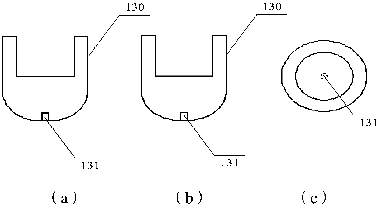
[0049] The coronary stent 200 can be stored in a centrifuge tube 300 filled with alcohol and placed approximately vertically. When it is necessary to take out the coronary stent 200 vertically from the centrifuge tube 300 and transfer it to another position for vertical placement, firstly, the clamp 100 can be gradually approached above the coronary stent 200 to be transferred, and then the stop device The circular limiting groove 131 on 130 faces the end of the coronary stent 200 close to the opening of the centrifuge tube 300 . Taking the coronary stent 200 with a weight of 54.34 mg as an example, the material of the limiting...
PUM
| Property | Measurement | Unit |
|---|---|---|
| Length | aaaaa | aaaaa |
| Diameter | aaaaa | aaaaa |
| Wall thickness | aaaaa | aaaaa |
Abstract
Description
Claims
Application Information