Refrigerant hammer arrestor and refrigerant loop incorporating that refrigerant hammer arrestor
A refrigerant circuit, refrigerant technology, applied in the direction of refrigeration and liquefaction, refrigerators, refrigeration components, etc.
- Summary
- Abstract
- Description
- Claims
- Application Information
AI Technical Summary
Problems solved by technology
Method used
Image

Examples
Embodiment Construction
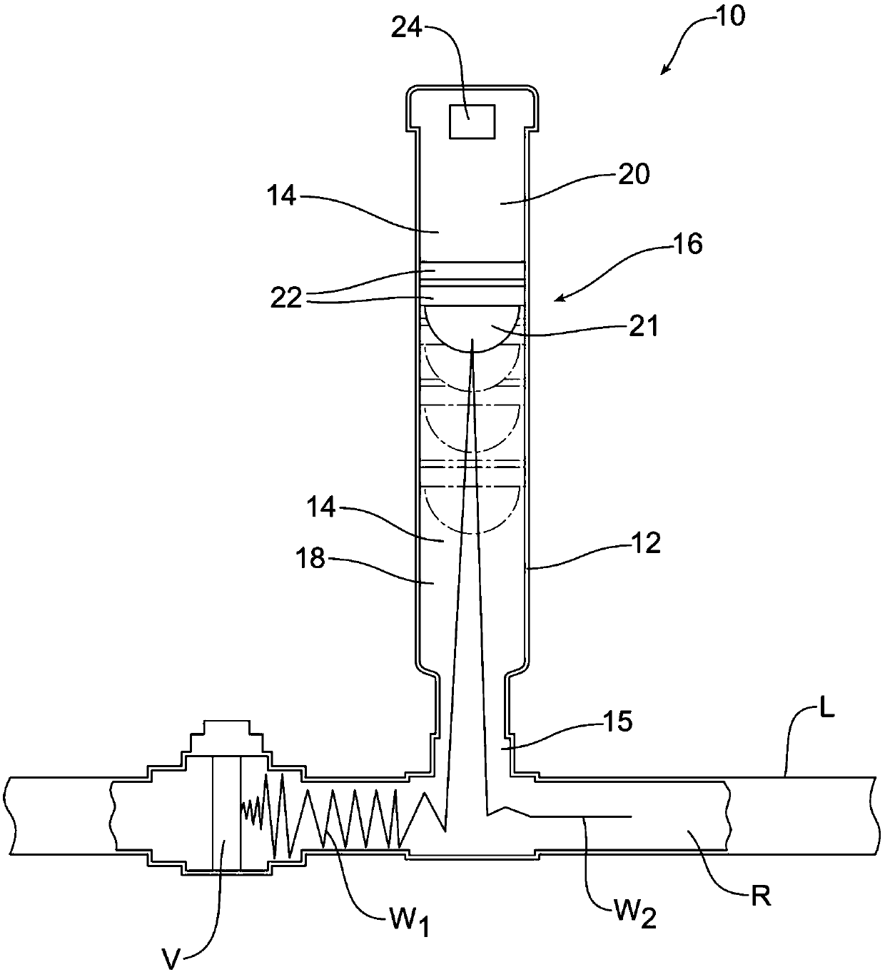
[0027] now refer to figure 1 , which schematically shows a new and improved refrigerant hammer eliminator 10 . The refrigerant hammer eliminator 10 includes a housing 12 . The housing 12 includes an internal compartment 14 . In the embodiment shown, said internal compartment 14 communicates with the refrigerant line L upstream of the shut-off valve V through an open end 15 . Piston 16 is received in housing 12 . The piston 16 divides the inner compartment 14 into a first chamber 18 and a second chamber 20 . In the illustrated embodiment, the piston 16 includes a hemispherical face 21 and two piston rings 22 for providing a smooth sliding action along the inner wall of the housing 12 .
[0028] A damping mechanism, generally indicated at 24 , is provided to slow displacement of the piston 16 within the housing 12 . In the illustrated embodiment, the damping mechanism 24 is arranged in the second chamber 20 .
[0029] The damping mechanism 24 is preferably a variable dampi...
PUM
 Abstract
Description
Claims
Application Information
PatSnap Eureka turns technology decisions into work you can execute. Powered by our Innovation Knowledge Graph, it runs expert workflows across engineering, life sciences, materials and intellectual property. Get your review-ready output in minutes.


