
Cooling system and method of motor and controller

A technology of generator controller and cooling system, which is applied in the direction of cooling/ventilation device, cooling/ventilation/heating transformation, power plant cooling combination arrangement, etc., which can solve the problems such as difficult to grasp the precise control algorithm and affecting the normal driving of the vehicle , to achieve the simplification of the pipeline, improve the heat dissipation effect and save the production cost

Active Publication Date: 2019-05-21
HUNAN CSR TIMES ELECTRIC VEHICLE
View PDF5 Cites 2 Cited by
  • Summary
  • Abstract
  • Description
  • Claims
  • Application Information

AI Technical Summary

Problems solved by technology

The disadvantage is that the water temperature will be delayed compared with the temperature of the generator, drive motor stator coil and the temperature of the generator controller and drive motor controller IGBT, and there will be a temperature difference, which will change with the driving conditions of the vehicle And changes, it is difficult to grasp the precise control algorithm
Therefore, in the actual driving process of the vehicle, the water temperature will not be high, but the generator, drive motor stator coil, generator controller, and drive motor controller IGBT have already experienced high temperature and power limitation, which affects the normal driving of the vehicle.

Method used


Image

  • Cooling system and method of motor and controller
  • Cooling system and method of motor and controller
  • Cooling system and method of motor and controller

Examples


Embodiment Construction

[0041] The present invention will be further described below in conjunction with accompanying drawing.

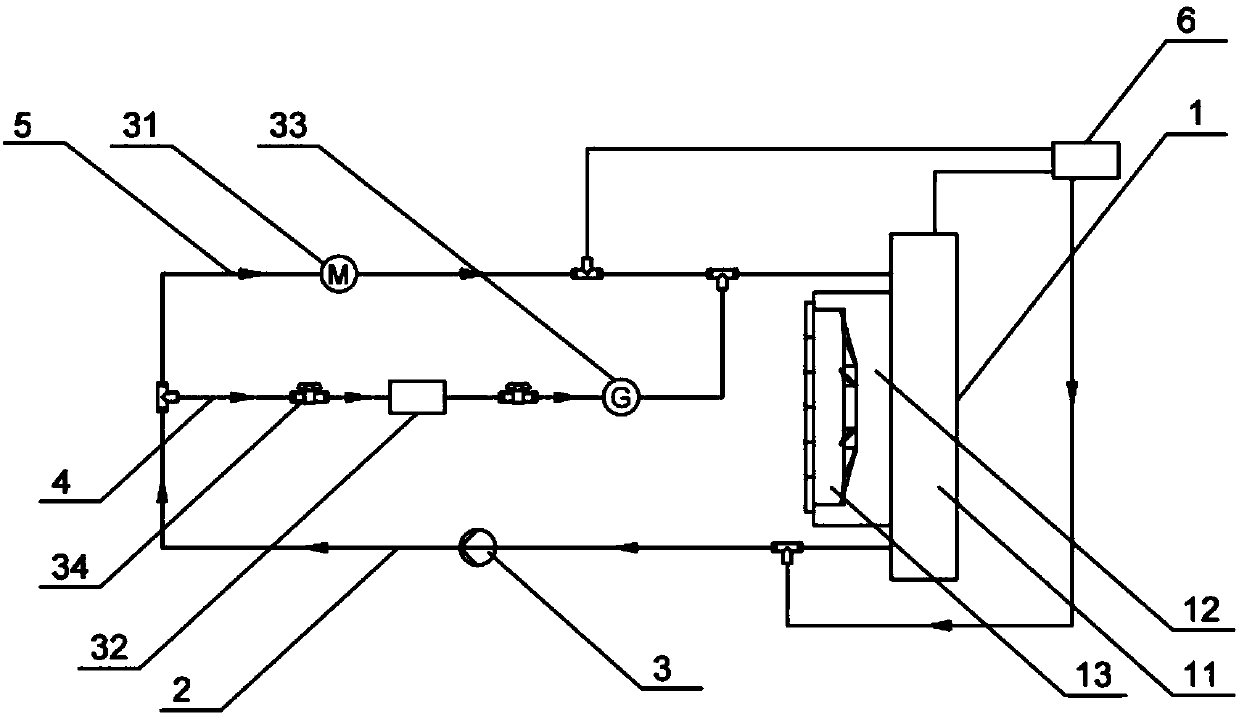
[0042] figure 1 A motor and controller cooling system according to one embodiment of the invention is schematically shown. According to the motor and controller cooling system of the present invention, a cooling system is used. At the same time, it can not only meet the flow and heat dissipation requirements of the integrated controller and generator, but also meet the flow and heat dissipation requirements of the drive motor.

[0043] Such as figure 1 As shown, the motor and controller cooling system described in this embodiment includes a cooling package assembly 1 . The cooling pack assembly 1 can be cooled down. The system described in this embodiment further includes a circulation loop 2, and both ends of the circulation loop 2 are respectively connected to the high-level interface and the low-level interface of the cooling pack assembly 1 . The circulation loop 2...

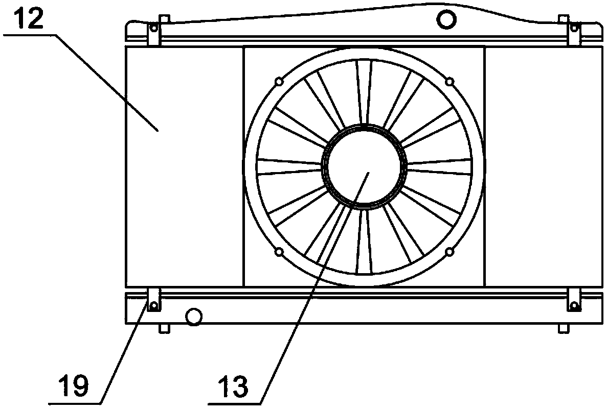
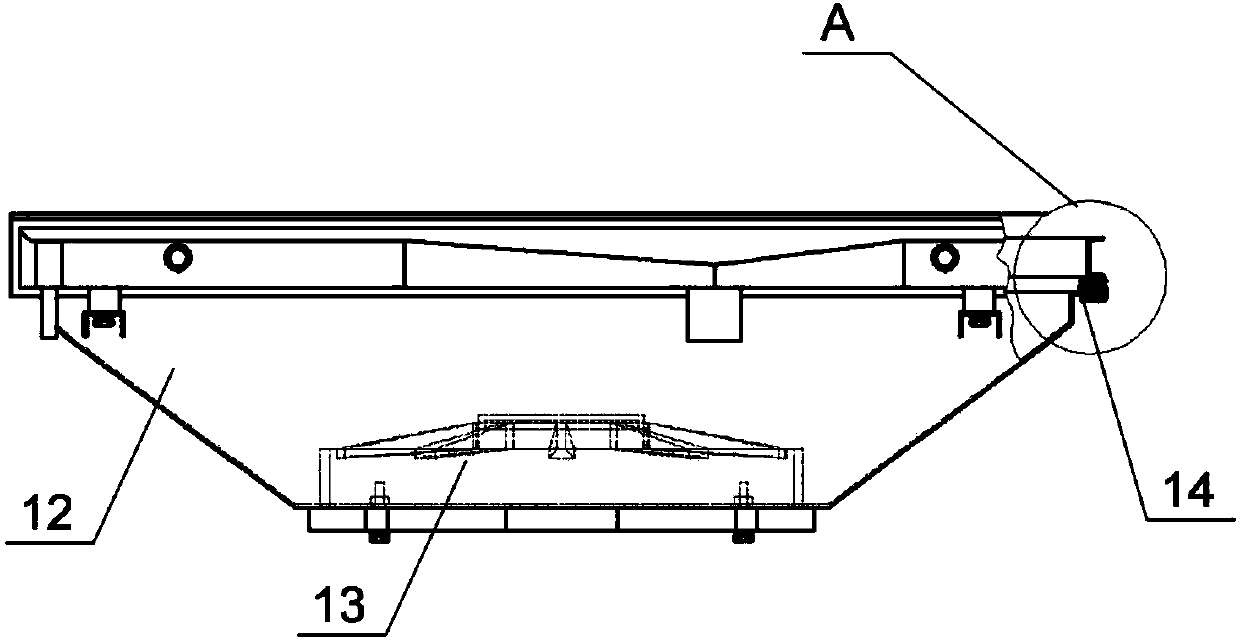

PUM


Abstract

The invention relates to a cooling system and method of a motor and a controller and belongs to the technical field of cooling of automobile driving systems. The system comprises a cooling bag assembly, a circulating loop and an expansion water tank; the two ends of the circulating loop are connected with a high-position connection port and low-position connection port of the cooling bag assemblyrespectively, and the circulating loop comprises water pumps connected in series, a first branch path and a second branch path, wherein the first branch path and the second branch path are connected with each other in parallel; the expansion water tank is connected with the cooling bag assembly and the circulating loop, wherein the first branch path comprises an integrated controller and a power generator which are arranged in series, and the integrated controller is positioned in front of the power generator. The second branch path includes a driving motor. By adopting the cooling system, thedemands of the controller and the power generator for flow and heat dissipation can be met at the same time, and the demands of the driving motor for flow and heat dissipation can also be met.

Description

technical field [0001] The invention relates to a cooling system and method for a motor and a controller, and belongs to the technical field of cooling of an automobile drive system. Background technique [0002] There are two main traditional cooling methods for current automotive electric drive systems. The first is that the generator and the drive motor are arranged in series, and the generator controller and the drive motor controller are arranged in series to form independent cooling systems. However, this method has the disadvantage of taking up a lot of space, and each cooling system uses a water pump, a radiator, and one or more electronic fans for heat dissipation, and the production cost is relatively high. The second is that the controller, the generator, and the drive motor are arranged in series to form a cooling system, and a water pump, a radiator, and one or more electronic fans are used for pumping and cooling. However, the disadvantage of this type of coo...

Claims


Application Information

Patent Timeline
IPC IPC(8): B60K11/02H02K9/19H05K7/20
Inventor 唐明忠陈煌熙周宏涛黎书萍张晨张彦斌王文闫冬龙爱军周宇马祥生
Owner HUNAN CSR TIMES ELECTRIC VEHICLE
Learn More