
Battery transfer device

A transfer device and battery technology, applied in electric power devices, power devices, transportation and packaging, etc., can solve the problems of unsatisfactory mechanical handling effect and inability to transfer power batteries, and achieve the effect of diversifying transportation methods and meeting the needs of transportation.

Pending Publication Date: 2019-05-21
BEIJING ELECTRIC VEHICLE +1
View PDF0 Cites 0 Cited by
  • Summary
  • Abstract
  • Description
  • Claims
  • Application Information

AI Technical Summary

Problems solved by technology

[0003] In the related technology, the way of transporting the power battery in the power station is manual handling or mechanical handling. Human handling will consume a lot of time and affect the efficiency of replacing the power battery. The effect of mechanical handling is not ideal, and the power battery cannot be quickly and stably transport

Method used


Image

  • Battery transfer device
  • Battery transfer device
  • Battery transfer device

Examples


Embodiment Construction

[0026] Embodiments of the present invention are described in detail below, examples of which are shown in the drawings, wherein the same or similar reference numerals designate the same or similar elements or elements having the same or similar functions throughout. The embodiments described below by referring to the figures are exemplary only for explaining the present invention and should not be construed as limiting the present invention.

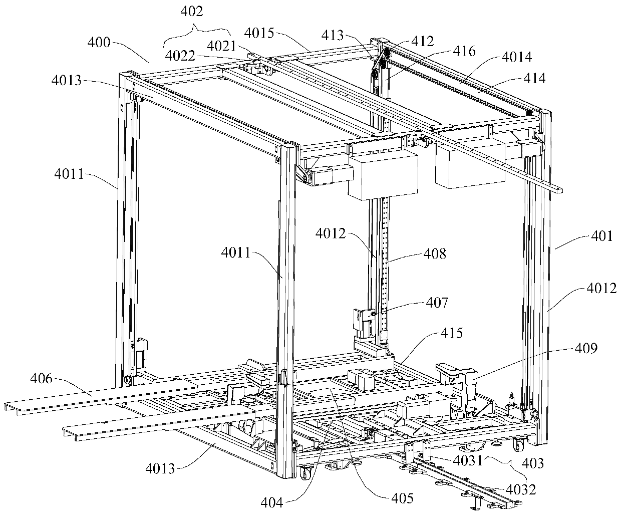
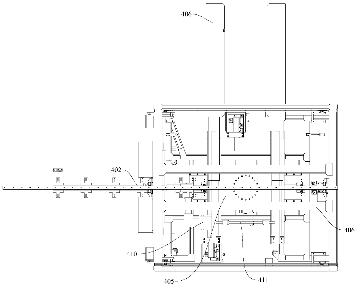
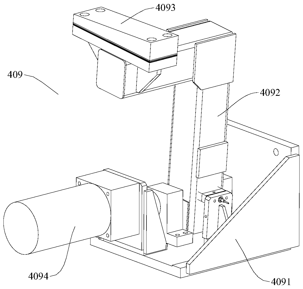
[0027] Refer below Figure 1-Figure 3 A battery transfer device 400 according to an embodiment of the present invention is described.

[0028] The battery transfer device 400 according to the embodiment of the present invention includes: a transfer device body, a mobile rotating platform 404 and a battery support frame 409 .

[0029] Wherein, the mobile rotary table 404 is rotatably installed on the transfer device body, and the mobile rotary table 404 can move in the horizontal direction and the vertical direction relative to the trans...


PUM


Abstract

The invention discloses a battery transfer device. The battery transfer device comprises a transfer device main body, a movable rotating table and a battery support frame. The movable rotating table is rotationally mounted on the transfer device main body; the movable rotating table can move in the horizontal direction and the vertical direction relative to the transfer device main body; and the battery support frame can be overturned relative to the transfer device main body to switch between a supported state and a folded state. Through cooperation between the movable rotating table and thebattery support frame, power batteries can be transported; and through the operating mode of the battery transfer device, the taking-out of the power batteries from multiple directions relative to thetransfer device main body can be realized, and the power batteries are transported to other directions, so that the transportation modes are diversified, and the transfer demands of the power batteries can be preferably met.

Description

technical field [0001] The invention relates to the technical field of battery replacement for new energy vehicles, in particular to a battery transfer device. Background technique [0002] At present, the emission of automobile exhaust is still an important factor of environmental pollution. In order to control automobile exhaust, electric vehicles have been popularized. The current electric vehicles mainly include direct charge and quick change. The power battery of the electric vehicle is quickly replaced by the power station. [0003] In the related technology, the way of transporting the power battery in the power station is manual handling or mechanical device handling. Human handling will consume a lot of time and affect the efficiency of replacing the power battery. The effect of mechanical handling is not ideal, and the power battery cannot be quickly and stably transport. Contents of the invention [0004] The present invention aims to solve at least one of th...

Claims


Application Information

Patent Timeline
IPC IPC(8): B65G35/00B65G47/82B60S5/06
Inventor 姚学诚李鹏飞郑飞鸽李玉军滕牧
Owner BEIJING ELECTRIC VEHICLE
Learn More