A tile lifting rack

A lifting frame and tile technology, applied in the direction of crowbars, lifting devices, etc., can solve the problems of easy arm fatigue, easy loss of water from cement, affecting tile laying, etc., and achieve the effect of reducing labor.

Active Publication Date: 2020-07-24
浙江年代建设工程有限公司
View PDF5 Cites 0 Cited by
  • Summary
  • Abstract
  • Description
  • Claims
  • Application Information

AI Technical Summary

Problems solved by technology

[0002] Ceramic tile is one of the common decorative materials in buildings. It is an acid and alkali resistant product formed by processing refractory metal oxides and semi-metal oxides. In order to make the ground more beautiful, it is necessary to lay ceramic tiles on the ground. Now generally, the staff manually lift the tiles, and then lay them on the cement to lay the tiles. When the tiles are large, the staff’s arms are prone to fatigue; in order to relieve the fatigue of the arms, the staff will stop working from time to time. It is easy to lose moisture and affect the laying of tiles

Method used


Image

  • A tile lifting rack
  • A tile lifting rack
  • A tile lifting rack

Examples


Embodiment 1

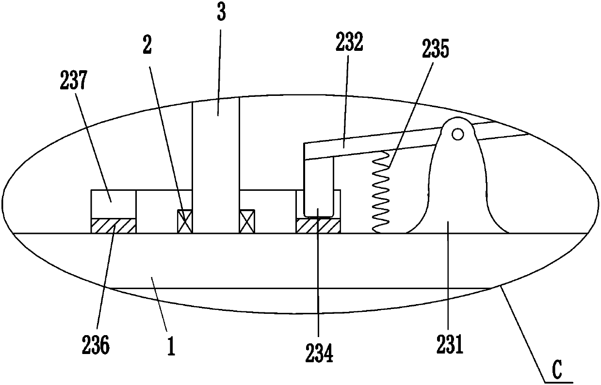
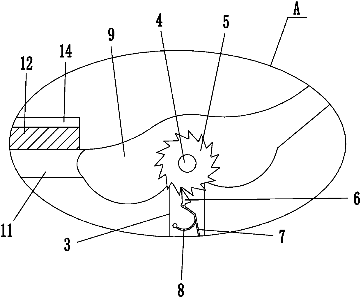
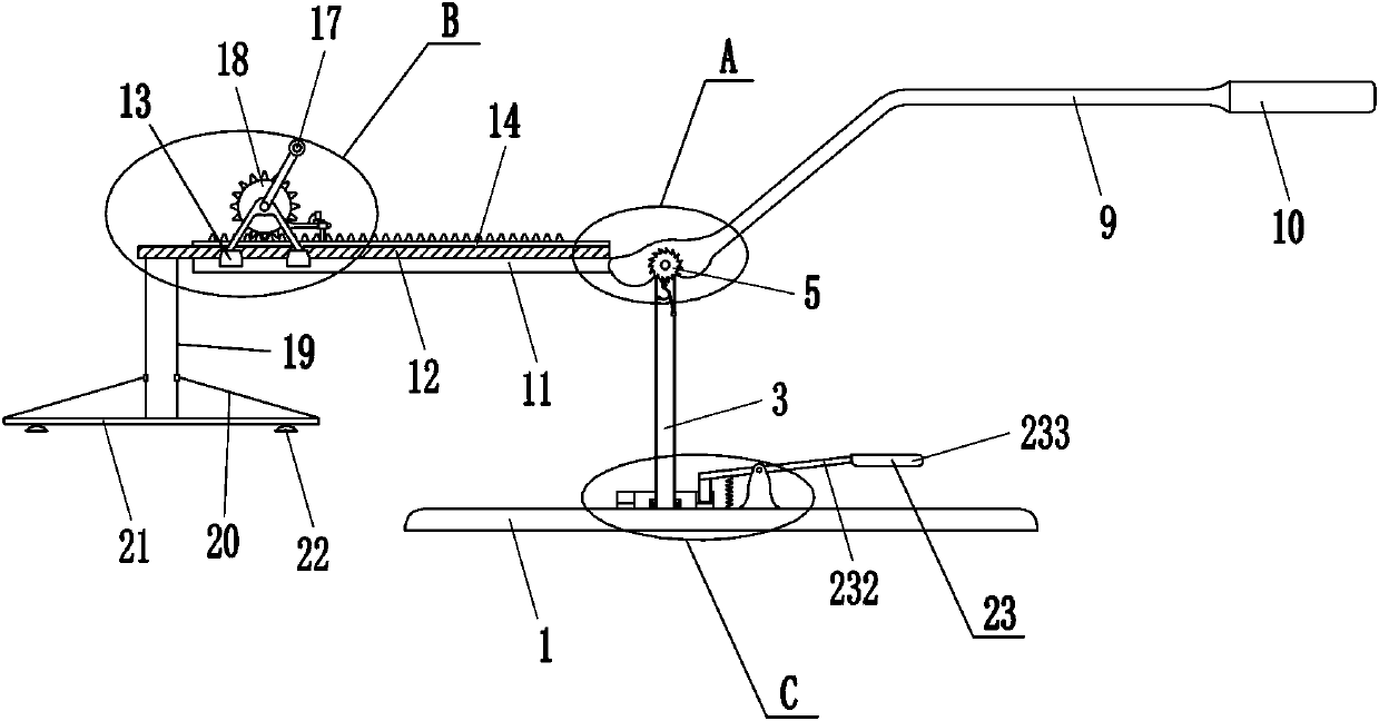
[0018] A tile lifting frame such as Figure 1-4 As shown, it includes a base 1, a bearing seat 2, a pole 3, a rotating shaft 4, a ratchet 5, a pawl 6, a lever 7, a shrapnel 8, a joystick 9, a handle 10, a cross bar 11, a slide rail 12, and a slider 13. Rack 14, bracket 15, rotating rod 16, rocking bar 17, gear 18, first stay cord 19, second stay cord 20, mounting plate 21 and suction cup 22, bearing seat 2 is installed on the left side of base 1 top, A support rod 3 is installed inside the bearing housing 2, a rotating shaft 4 is installed on the upper part of the supporting rod 3, and a ratchet 5 is installed on the front part of the rotating shaft 4. meshing, the bottom end of the ratchet 6 is connected with a driving lever 7, and a shrapnel 8 is connected between the left side of the driving lever 7 and the upper left side of the front side of the support rod 3, a joystick 9 is installed at the rear end of the rotating shaft 4, and a handle is installed at the right end of ...

Embodiment 2

[0020] A tile lifting frame such as Figure 1-4 As shown, it includes a base 1, a bearing seat 2, a pole 3, a rotating shaft 4, a ratchet 5, a pawl 6, a lever 7, a shrapnel 8, a joystick 9, a handle 10, a cross bar 11, a slide rail 12, and a slider 13. Rack 14, bracket 15, rotating rod 16, rocking bar 17, gear 18, first stay cord 19, second stay cord 20, mounting plate 21 and suction cup 22, bearing seat 2 is installed on the left side of base 1 top, A support rod 3 is installed inside the bearing housing 2, a rotating shaft 4 is installed on the upper part of the supporting rod 3, and a ratchet 5 is installed on the front part of the rotating shaft 4. meshing, the bottom end of the ratchet 6 is connected with a driving lever 7, and a shrapnel 8 is connected between the left side of the driving lever 7 and the upper left side of the front side of the support rod 3, a joystick 9 is installed at the rear end of the rotating shaft 4, and a handle is installed at the right end of ...

Embodiment 3

[0023] A tile lifting frame such as Figure 1-4As shown, it includes a base 1, a bearing seat 2, a pole 3, a rotating shaft 4, a ratchet 5, a pawl 6, a lever 7, a shrapnel 8, a joystick 9, a handle 10, a cross bar 11, a slide rail 12, and a slider 13. Rack 14, bracket 15, rotating rod 16, rocking bar 17, gear 18, first stay cord 19, second stay cord 20, mounting plate 21 and suction cup 22, bearing seat 2 is installed on the left side of base 1 top, A support rod 3 is installed inside the bearing housing 2, a rotating shaft 4 is installed on the upper part of the supporting rod 3, and a ratchet 5 is installed on the front part of the rotating shaft 4. meshing, the bottom end of the ratchet 6 is connected with a driving lever 7, and a shrapnel 8 is connected between the left side of the driving lever 7 and the upper left side of the front side of the support rod 3, a joystick 9 is installed at the rear end of the rotating shaft 4, and a handle is installed at the right end of t...


PUM


Abstract

The invention relates to a hanger, in particular to a tile hanger. The tile hanger can reduce the labor amount of workers. The tile hanger comprises a base, a bearing seat, a supporting rod, a rotating shaft, a ratchet wheel, a pawl, a deflector rod, an elastic sheet, an operating rod, a handle, a cross rod, a sliding rail, a sliding block, gear racks and the like; the bearing seat is installed onthe left side of the top of the base, the supporting rod is installed in the bearing seat, the rotating shaft is rotatably installed on the upper part of the supporting rod, the ratchet wheel is installd at the front of the rotating shaft, the pawl is rotatably connected to the upper part of the front side of the supporting rod, the pawl meshes the ratchet wheel, the deflector rod is connected tothe bottom end of the pawl, the elastic sheet is connected between the left side of the deflector rod and the left upper part of the front side of the supporting rod, and the operating rod is installed at the rear end of the rotating shaft. According to the tile hanger, an installation plate can be driven to move upwards by pressing the handle downwards, so that a tile is hoisted, a worker is notrequired to manually carry the tile, and the labor amount of the worker can be reduced; and the supporting rod can be fixed through a clamping mechanism, so that the tile is prevented from deviatingfrom the position caused by the rotation of the supporting rod.

Description

technical field [0001] The invention relates to a lifting frame, in particular to a ceramic tile lifting frame. Background technique [0002] Ceramic tile is one of the common decorative materials in buildings. It is an acid and alkali resistant product formed by processing refractory metal oxides and semi-metal oxides. In order to make the ground more beautiful, it is necessary to lay ceramic tiles on the ground. Now generally, the staff manually lift the tiles, and then lay them on the cement to lay the tiles. When the tiles are large, the staff’s arms are prone to fatigue; in order to relieve the fatigue of the arms, the staff will stop working from time to time. It is easy to lose moisture and affect the laying of tiles. Contents of the invention [0003] In order to overcome the shortcoming that the staff needs to manually lift the tiles, and then lay them on the paved cement to lay the tiles, and the staff's arms are prone to fatigue, the technical problem is to pro...

Claims


Application Information

Patent Timeline
Patent Type & Authority Patents(China)
IPC IPC(8): B66F15/00
Inventor 刘德塬
Owner 浙江年代建设工程有限公司
Why Eureka
Try Eureka