Rotary drum and workpiece processing device

A technology for drums and components, applied in the field of drums and workpiece processing devices, which can solve the problems of reducing the inner cavity, reducing the processing capacity of workpieces in the drum, and affecting the working efficiency of the drum, etc.

Pending Publication Date: 2019-05-21
KUNSHAN DONGWEI MACHINERY CO LTD
View PDF1 Cites 0 Cited by
  • Summary
  • Abstract
  • Description
  • Claims
  • Application Information

AI Technical Summary

Problems solved by technology

[0006] Or, when the radial height of the drum is not changed, the axial length of the drum is shortened so that most of the workpieces thrown by the drum fall on the top surface of the conveying mechanism, but the axial length of the drum is shortened , will reduce the inner cavity of the barrel body, the amount of workpieces that can be carried by the inner cavity is low, and the processing capacity of workpieces in the drum will be reduced, which will also affect the working efficiency of the drum
That is to say, it is difficult for the drum in the prior art to avoid the phenomenon that the workpiece sticks to the conveying mechanism without reducing the amount of the workpiece carried by the drum, so that the unloading speed of the drum is fast and the unloading is clean.

Method used


Image

  • Rotary drum and workpiece processing device
  • Rotary drum and workpiece processing device
  • Rotary drum and workpiece processing device

Examples


Embodiment 1

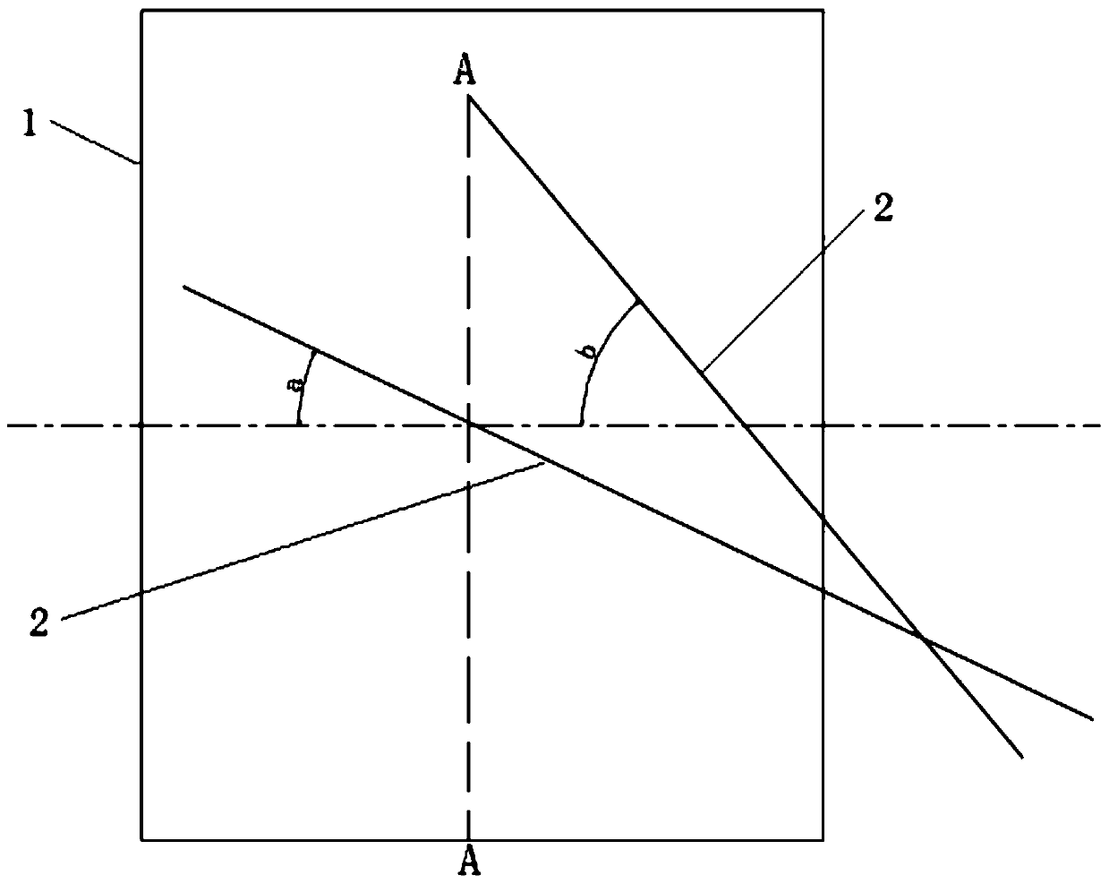
[0065] This embodiment provides a drum, such as Figure 2 to Figure 9 As shown, it includes a bucket body 1 and a conveying mechanism 2 , wherein the bucket body 1 is rotatably arranged on a frame 7 in such a way that the discharge steering and the working steering can be changed.

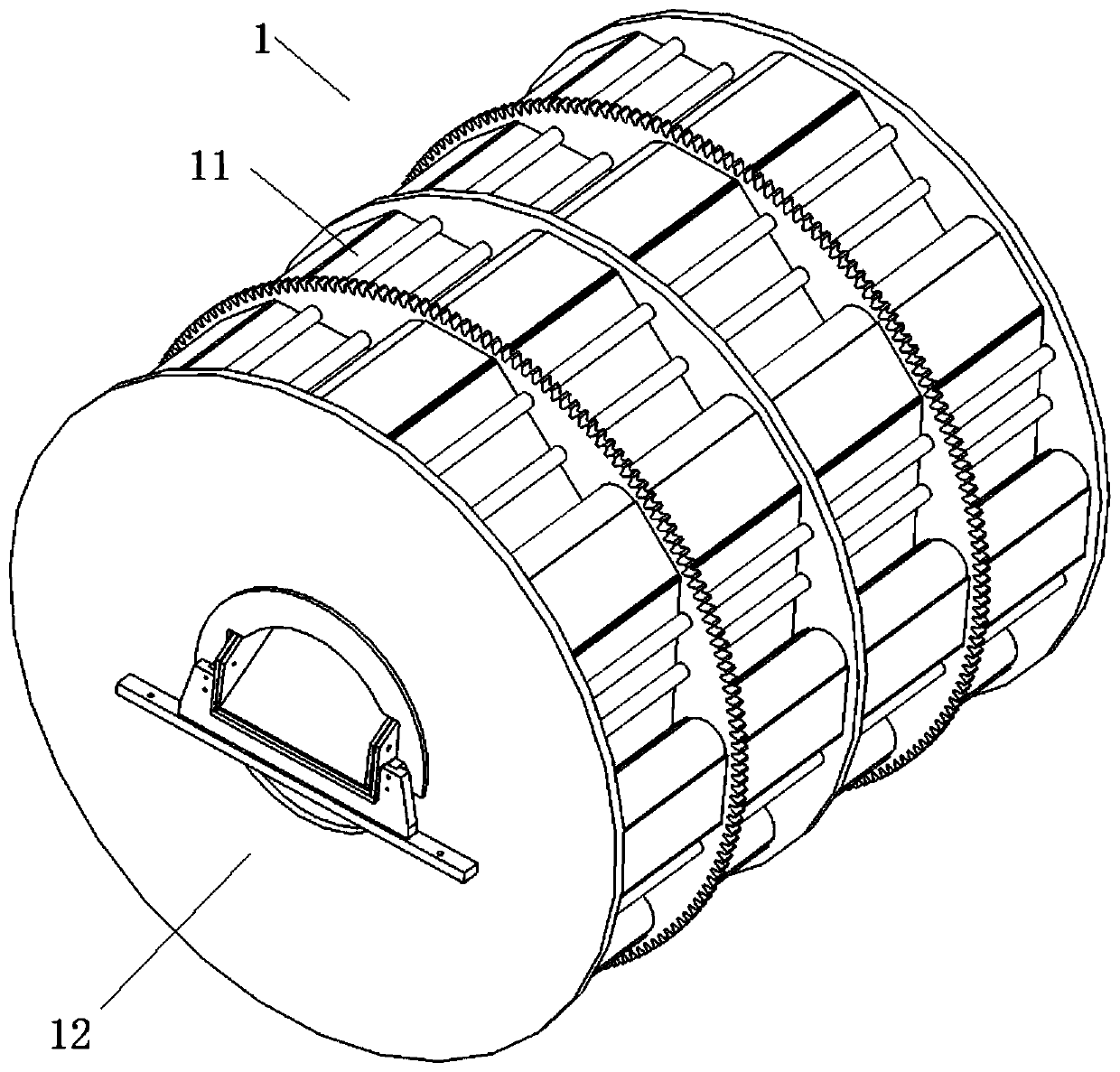
[0066] Such as Figure 4 As shown, the bucket body 1 includes a cylinder body 11, two side baffles 12 and a scoop member 5, wherein the two side baffles 12 are mounted on the frame 7, and the axial ends of the cylinder 11 are open, and the bucket The axial ends of the main body 1 are respectively rotatably arranged on the corresponding side baffles 12 and form a working inner cavity with the two side baffles 12, so that the barrel body 1 is rotatably arranged on the frame 7 On; the two side baffles 12 are respectively provided with a feed port 121 and a discharge port 122 .

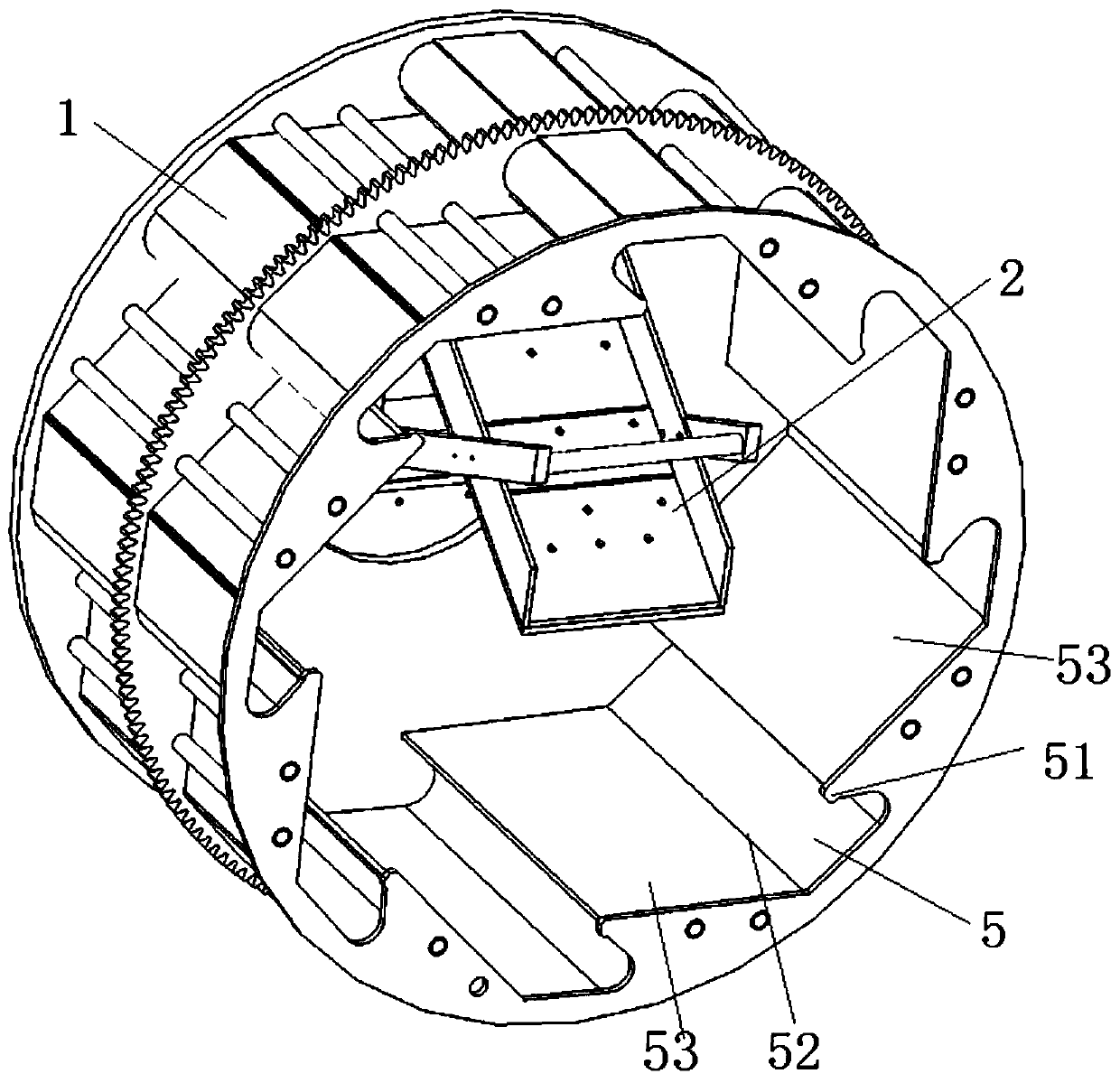
[0067] As for the scooping material 5 , the scooping material 5 can be provided as the inner wall of the cylinder 11 , or ...

Embodiment 2

[0089] This embodiment provides a drum. Compared with the drum provided in Embodiment 1, the difference is that the number of sliding material parts 21 provided by the conveying mechanism is different, and other structures are the same as in Embodiment 1. Please refer to Embodiment 1.

[0090] Specifically, in this embodiment, the conveying mechanism has three, four, five, six, seven and so on a plurality of sliding material members 21 . That is, at least one sliding material part 21 is also arranged between the first sliding material part and the second sliding material part in embodiment 1, and among all the sliding material parts 21, the first sliding material part is at the starting position, and the second sliding material part is at the initial position. The second sliding material part is located at the end position, except for the second sliding material part, all other sliding material parts 21 are arranged in the inner cavity of the barrel body.

[0091] Among the p...

Embodiment 3

[0100] This embodiment provides a workpiece processing device, for example, the workpiece processing device is an electroplating device, or a cleaning device, and its workpiece processing device includes the drum provided in Embodiment 1 or Embodiment 2, such as Figure 10 As shown, the drum is rotatably arranged in the tank body 4. For example, a drive motor is arranged on the frame 7, a drive gear is fixed on the output shaft of the drive motor, and a ring gear is arranged on the circumferential outer wall of the drum. The driving gear meshes with the ring gear, so that when the driving motor rotates in the forward direction, the barrel body 1 is driven to be in the working direction, and when the driving motor is rotated in the reverse direction, the barrel body 1 is driven in the discharging direction.

[0101] In the workpiece processing device of this embodiment, since the drum of embodiment 1 or embodiment 2 is used, the workpiece processing device can ensure the bearing...


PUM


Abstract

The invention provides a rotary drum and a workpiece processing device. The rotary drum comprises a drum body and a conveying mechanism. The conveying mechanism comprises multiple material sliding parts. The material sliding parts are arrayed and arranged in the axial direction of the drum body and incline downwards in the direction from a feed port of the drum body to a discharge port. The workpiece processing device comprises the rotary drum mentioned above. The multiple material sliding parts are arranged, the first angle at which each material sliding part inclines downwards is set to be larger, and therefore in the process that workpieces slide on the material sliding parts, the component force, in the inclining direction of the material sliding parts, of the gravity of the workpiecesthemselves is increased and is larger than the viscous force, on the corresponding material sliding parts, of the workpieces, the workpieces can smoothly slide downwards under the effect of the gravity of the workpieces themselves, and it is avoided that the workpieces adhere to the material sliding parts; and meanwhile, by means of the multiple material sliding parts, the workpiece close to theposition of the feed port is transferred to the position below the material sliding part close to the position of the discharge port step by step, the phenomenon that the workpieces adhere to the material sliding parts is avoided while the bearing capacity is not decreased, and the discharge speed and the discharge completeness of the rotary drum are increased.

Description

technical field [0001] The invention relates to the technical field of electroplating, in particular to a drum and a workpiece processing device. Background technique [0002] Barrel plating and barrel electroplating are to place a certain number of small parts in a special barrel, and deposit various metal or alloy coatings on the surface of the parts in a way of indirect conduction in the barrel plating state, so as to achieve surface protection and decoration. An electroplating processing method for a functional purpose. [0003] For example, a drum disclosed in the Chinese patent document CN 208275859 U is provided with a feed port and a discharge port on both axial ends of the drum respectively, and the conveying port that is installed on the discharge port and fixed on the frame Mechanism, the conveying mechanism is arranged downwards from the feed port to the discharge port, the top of the conveying mechanism extends into the drum, and its bottom protrudes out of the...

Claims


Application Information

Patent Timeline
Patent Type & Authority Applications(China)
IPC IPC(8): C25D17/20
Inventor 危勇军方志斌朱康利
Owner KUNSHAN DONGWEI MACHINERY CO LTD
Why Eureka
Try Eureka