A combined diversion device for improving the flow state of the inlet pool of a lateral inlet pumping station

A technology of diversion device and water inlet pool, which is applied in the direction of ship lifting device, river improvement, construction, etc., and can solve the problem of inability to fully guarantee the water absorption conditions and stable operation of the water pump in the lateral inflow pumping station, uneven pressure distribution, and insufficient effect Ideal and other problems, to improve the flow velocity distribution and pressure distribution conditions, solve the mainstream deflection, and achieve the effect of novel device structure

Active Publication Date: 2020-07-31
YANGZHOU UNIV
View PDF5 Cites 0 Cited by
  • Summary
  • Abstract
  • Description
  • Claims
  • Application Information

AI Technical Summary

Problems solved by technology

[0004] The purpose of the present invention is to solve the relatively special layout of the current lateral water inlet pumping station, and the deflection of the mainstream in the water inlet pool is inevitable, which can reach 90° in severe cases, resulting in uneven pressure distribution, lateral flow in the water inlet pool, and serious vortices Or backflow, poor water absorption conditions, often accompanied by running vibration and noise, etc., and the current rectification measures to improve the bad flow state in the inlet pool mainly include diversion piers, columns and pressure water plates, and the effect of these rectification measures is not ideal. The water absorption conditions and stable operation of the pumps in the lateral inflow pumping station cannot be fully guaranteed. A combined diversion device is proposed to improve the flow state of the inlet pool of the lateral inflow pumping station. The problems of mainstream deflection, lateral flow and severe vortex in the pool can improve the stability of pumping station operation

Method used


Image

  • A combined diversion device for improving the flow state of the inlet pool of a lateral inlet pumping station
  • A combined diversion device for improving the flow state of the inlet pool of a lateral inlet pumping station
  • A combined diversion device for improving the flow state of the inlet pool of a lateral inlet pumping station

Examples


Embodiment Construction

[0019] The present invention will be further described below in conjunction with accompanying drawing:

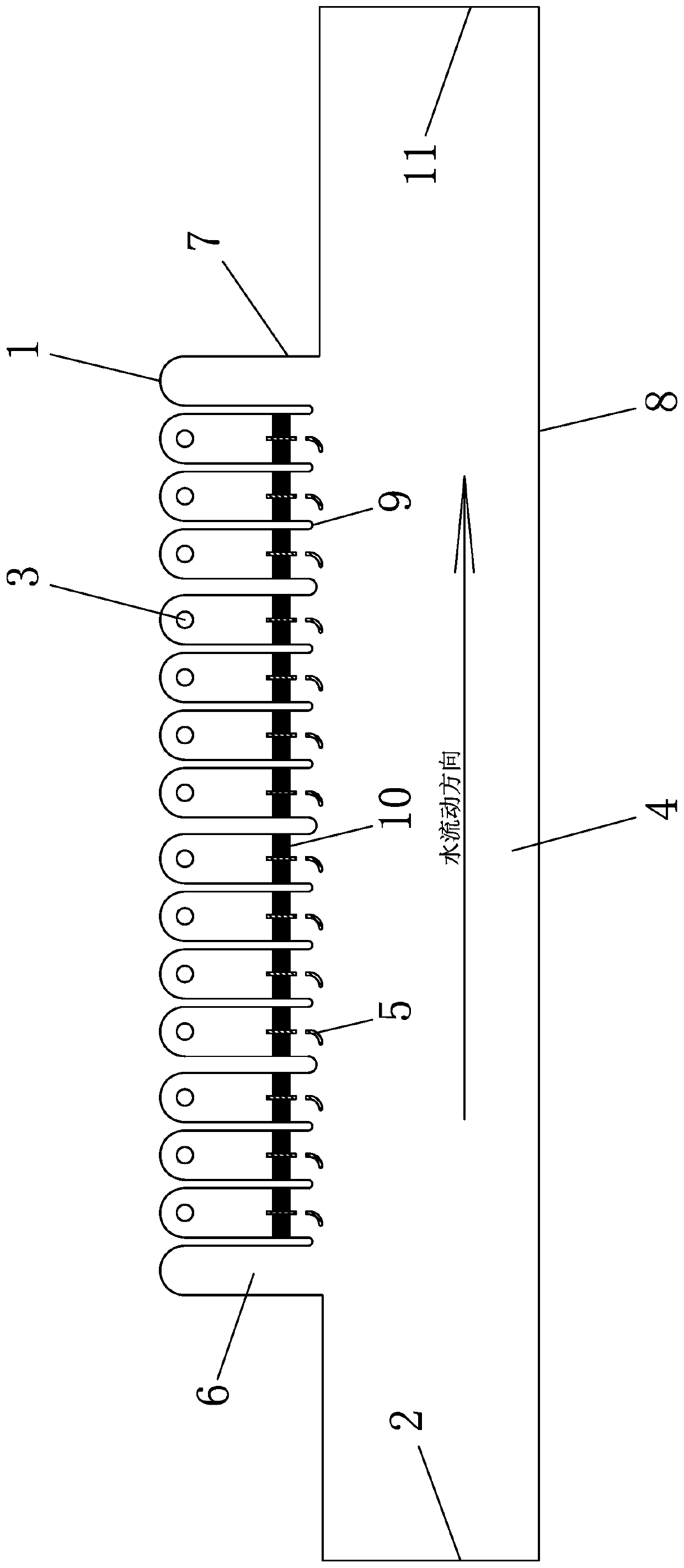
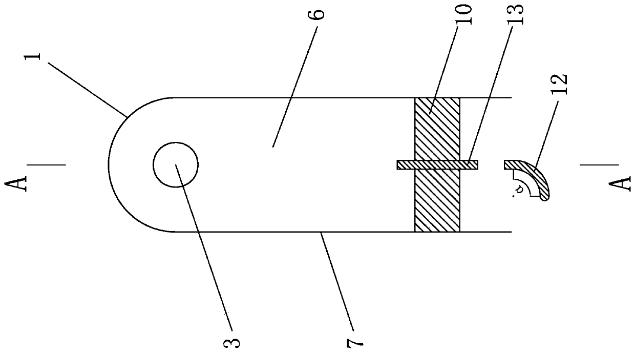
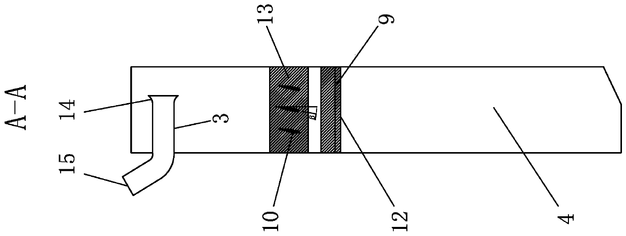
[0020] Such as Figure 1-3 As shown, a combined diversion device for improving the flow state of the water inlet tank of a lateral inflow pumping station includes a river channel 4 formed by a diversion channel 2, a gate 11 and a side slope 8; one side of the river channel 4 is provided with several side-by-side inlets. The water pool 6 and the water inlet pool 6 are composed of the wing wall 7 and the water inlet pool rear wall 1. A partition pier 9 is arranged between the water inlet pool 6 and the water inlet pool 6, and a J-shaped diversion pier 5 and an adjustable wing are arranged at the entrance of the water inlet pool 6. Type diversion crosspiece 10, the inside of the inlet pool 6 is provided with a water pump suction pipe 3 near the rear wall of the inlet pool 1, and the J-type diversion pier 5 is composed of an arc diversion pier section 12 with an angle α and a s...


PUM


Abstract

A combined diversion device for improving the flow state of the inlet pool of a lateral inflow pumping station, which belongs to the field of water transfer technology for water conservancy and municipal engineering pumping stations. A J-shaped diversion pier and an adjustable The airfoil diversion crosspiece, through the arc diversion pier of the J-shaped diversion pier, the water in the river channel is smoothly introduced into the water inlet pool, and the gap between the arc diversion pier and the straight diversion pier can balance the two sides of the diversion pier The water volume should be as consistent as possible on both sides; the straight diversion pier can further divert the water flow, and the adjustable airfoil diversion crosspiece can respectively guide the water flow in the inner surface layer, middle layer and bottom layer of the inlet pool. Avoid the occurrence of longitudinal flow, improve the flow velocity distribution and pressure distribution conditions in the inlet pool, make the water flow smoothly to the water pump inlet, and effectively solve the mainstream deflection, lateral flow and serious vortex in the inlet pool of the lateral inlet pump station The problem of improving the stability of the pumping station operation.

Description

technical field [0001] The invention belongs to the technical field of pumping station water diversion in water conservancy projects and municipal engineering, and relates to a flow guide device for a water inlet pool, in particular to a combined flow guide device for improving the flow form of a water inlet pool of a lateral water inlet pump station. Background technique [0002] In order to ensure the smoothness of the water flow, the pump station should be arranged as a positive water inlet. When the positive water inlet arrangement cannot be adopted due to factors such as terrain conditions, civil engineering scale and planning functions, a side water inlet pump station is required. . The water intake structures of the lateral water inlet pumping station include diversion channels, forebays, wing walls, water inlet pools and pier, etc. Most of the small and medium-sized pumping stations adopt the form of lateral water inlet. Since the inflow direction of the inlet tank ...

Claims


Application Information

Patent Timeline
Patent Type & Authority Patents(China)
IPC IPC(8): E02B3/02E02C1/06
Inventor 罗灿刘浩刘超成立袁尧金燕杨帆王瑄焦伟轩
Owner YANGZHOU UNIV
Why Eureka
Try Eureka