
micro flow sensor

A flow sensor, sensor technology, applied in the measurement of flow/mass flow, liquid/fluid solid measurement, instruments, etc., can solve problems such as difficulty in miniaturization

Active Publication Date: 2016-02-24
YOKOGAWA ELECTRIC CORP
View PDF9 Cites 0 Cited by
  • Summary
  • Abstract
  • Description
  • Claims
  • Application Information

AI Technical Summary

Problems solved by technology

When the run-up section is long, it is difficult to downsize the entire device incorporating the flow sensor

Method used


Image

  • micro flow sensor
  • micro flow sensor
  • micro flow sensor

Examples


Embodiment Construction

[0049] In the following detailed description, for purposes of explanation, numerous specific details are set forth in order to provide a thorough understanding of the disclosed embodiments. It may be evident, however, that one or more embodiments may be practiced without these specific details. In other instances, well-known structures and devices are shown schematically in order to simplify the drawings.

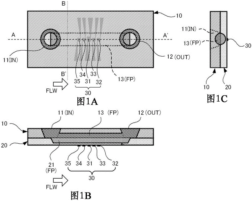
[0050] Figure 1A ~ Figure 1C It is a structural explanatory diagram showing an example of the minute flow sensor (this flow sensor) of this embodiment. Figure 1A for top view, Figure 1B for Figure 1A A-A' sectional view of . Figure 1C for Figure 1A The B-B' section view.

[0051] Such as Figure 1A ~ Figure 1C As shown, the substrate (first substrate) 10 and substrate (second substrate) 20 of the flow sensor are bonded together by bonding.

[0052] The two substrates 10 and 20 are made of glass such as Pyrex (registered trademark). The two substrates 10 and 2...


PUM


Abstract

The present invention provides a micro flow sensor, which includes: a flow path through which a fluid to be measured flows; a detection unit having a heater for heating the fluid to be measured in the flow path; and a device for measuring the fluid to be measured in the flow path. a temperature sensor of temperature; a calculation unit for measuring the flow rate of the measurement target fluid flowing through the flow path based on the temperature of the measurement target fluid measured by the temperature sensor; and a throttle unit provided in the The flow path is located upstream of the detection part, and the flow path is narrowed.

Description

[0001] Cross References to Related Applications [0002] This application claims the priority of Japanese Patent Application No. 2012-124744 filed with the Japan Patent Office on May 31, 2012, and therefore the entire content of said Japanese Patent Application is incorporated herein by reference. technical field [0003] The invention relates to a tiny flow sensor. Background technique [0004] Micro flow sensors measure the flow of fluid by detecting the movement of heat in the fluid. Conventionally, various micro flow sensors in which a flow path and a detection unit are integrated have been disclosed. For example, "Tanaka Hitoaki, Wai Sanmei, "Micro Flow Sensa for Microflow Acta System", Yokogawa Technical Report, Yokogawa Electric Corporation, 2008, Vol.52No.4(2008) p.39-42 (Tanaka Hitoaki , and three others, "Miniature Flow Sensors for Microreactor Systems, Yokogawa Technical Report, Yokogawa Electric Corporation, 2008, Vol.52No.4 (2008) p.39-42)" and Japanese Patent...

Claims


Application Information

Patent Timeline
Patent Type & Authority Patents(China)
IPC IPC(8): G01F1/68
CPCG01F1/6842G01F1/6845G01F1/6847G01F15/00G01F15/14G01F1/684G01F1/692
Inventor 田中仁章寺尾美菜子田中宏明
Owner YOKOGAWA ELECTRIC CORP
Learn More