
Rigid high-precision hydraulic synchronous device

A hydraulic synchronization and high-precision technology, applied in the direction of fluid pressure actuators, servo motors, mechanical equipment, etc., can solve problems such as unbalanced force, damage, and partial load, and achieve high reliability, simple control, and synchronization accuracy high effect

Active Publication Date: 2019-05-21
煤科(北京)检测技术有限公司
View PDF4 Cites 2 Cited by
  • Summary
  • Abstract
  • Description
  • Claims
  • Application Information

AI Technical Summary

Problems solved by technology

However, in the application practice of multi-cylinder synchronous loading, it is often difficult to realize multi-cylinder synchronous loading due to factors such as the accuracy and error of control components, resulting in unbalanced loads, unbalanced forces, and even mechanical structural parts being stuck and damaged.

Method used


Image

  • Rigid high-precision hydraulic synchronous device

Examples


Embodiment Construction

[0012] In the description of the present invention, it should be understood that the orientation or positional relationship indicated by the terms "upper", "lower", "left", "right" etc. is based on the orientation or positional relationship shown in the drawings, and is only for convenience The present invention is described and simplified descriptions do not indicate or imply that the device or element referred to must have a specific orientation, be constructed and operate in a specific orientation, and thus should not be construed as limiting the present invention. The present invention will be described in detail below in conjunction with the accompanying drawings and embodiments.

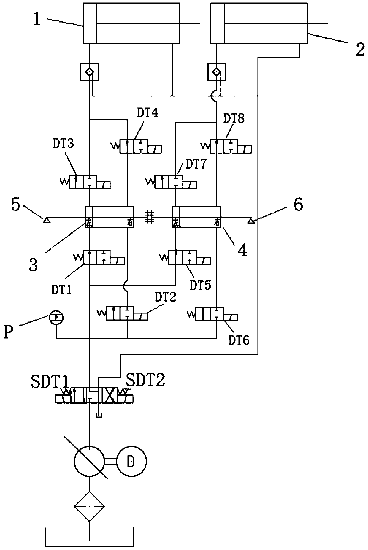
[0013] Such as figure 1 As shown, the present invention provides a rigid high-precision hydraulic synchronous device, which includes a first hydraulic cylinder 1, a second hydraulic cylinder 2, a first synchronous cylinder 3, a second synchronous cylinder 4, a first control valve group, a secon...


PUM


Abstract

The invention relates to a rigid high-precision hydraulic synchronous device. The lower portions of a left cavity and a right cavity of a first synchronous cylinder are connected with one end of a first control valve group. The other end of the first control valve group is connected with a pressure gauge and the output end of the high-pressure oil tank. The output end of the high-pressure oil tankis provided with an electromagnetic reversing valve. The lower portions of a left cavity and a right cavity of a second synchronous cylinder are both connected with one end of a second control valvegroup. The other end of the second control valve group is connected with the pressure gauge and the output end of the high-pressure oil tank. The upper portions of the left cavity and the right cavityof the first synchronous cylinder are both connected with one end of the third control valve group. The other end of the third control valve group is connected with the left cavity of a first hydraulic cylinder through a hydraulic pipeline. The upper portions of the left cavity and the right cavity of the second synchronous cylinder are connected with one end of a fourth control valve group. Theother end of the fourth control valve group is connected with the left cavity of a second hydraulic cylinder through a hydraulic pipeline. The right cavity of the first hydraulic cylinder and the right cavity of the second hydraulic cylinder are connected in parallel through a hydraulic pipeline and then are connected with the output end of the high-pressure oil tank through an electromagnetic reversing valve. The rigid high-precision hydraulic synchronous device can rigidly guarantee that the hydraulic cylinders needing adjustment synchronously act.

Description

technical field [0001] The invention relates to the field of synchronous control of hydraulic oil cylinders, in particular to a rigid and high-precision hydraulic synchronous device. Background technique [0002] Hydraulic cylinders are hydraulic components widely used in industrial and agricultural industries. They are often used in hydraulic pressure loading, platform lifting and other occasions. They have the obvious advantages of simple operation, economical and practical, and high reliability. With the large-scale and heavy-duty mechanical products, there are more and more requirements for the working resistance of hydraulic cylinders. As we all know, the working resistance of a hydraulic cylinder is directly proportional to the cylinder diameter. Under the same pressure conditions, the larger the cylinder diameter, the greater the working resistance. However, due to the larger bore of the hydraulic cylinder, its processing difficulty and cost have increased significan...

Claims


Application Information

Patent Timeline
Patent Type & Authority Applications(China)
IPC IPC(8): F15B11/22
Inventor 刘欣科赵锐王世超崔述凯沙宝银牛一村赵越
Owner 煤科(北京)检测技术有限公司
Learn More