Bulb-type multipurpose variable transmission device and transmission mode based on same
A transmission device, multi-purpose technology, applied in the direction of transmission device, belt/chain/gear, mechanical equipment, etc., can solve the problems of many friction points and energy consumption points in the transmission link, difficulty in starting the working machine, and single transmission mode, etc. Easy coupling and transmission, strong power, and the effect of improving transmission efficiency
- Summary
- Abstract
- Description
- Claims
- Application Information
AI Technical Summary
Problems solved by technology
Method used
Image
Examples
Embodiment 1
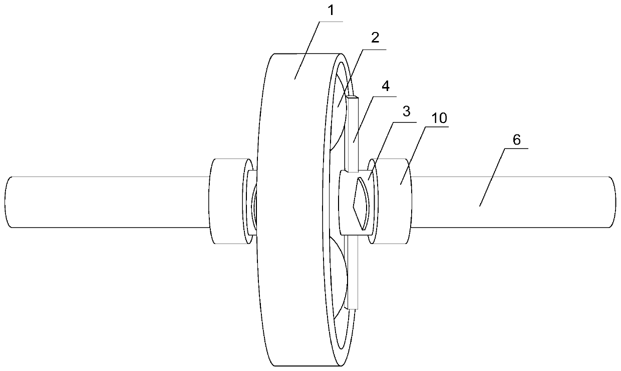
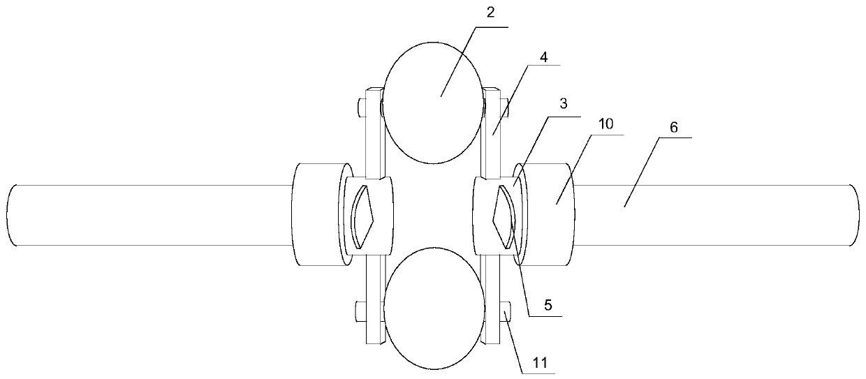
[0033] like figure 1 , figure 2 , image 3 As shown, a ball handle type multi-purpose variable transmission device of the present invention includes a button device, an arm ring spoke device connected with the button device, and a transmission short shaft 6 connected with the arm ring spoke device, and the button The device includes a ring gear 1, at least two steel balls 2 installed on the inner wall of the ring gear 1, and all the steel balls 2 are evenly distributed along the inner wall of the ring gear 1; 4. The iron handle 5 and the energy-gathering ring sleeve 3 are cylinders coaxial with the ring gear 1. Each steel ball 2 is connected and fixed with the energy-gathering ring sleeve 3 through a power arm 4 respectively. The power arm 4 and the steel ball 2 are connected together. One corresponding connection, one end of the power arm 4 is connected with the steel ball 2, the other end of the power arm 4 is fixed on the energy-gathering ring 3, all the power arms 4 are...
Embodiment 2
[0040] Based on Embodiment 1, an inner square hole 7 is provided at one end of the energy-collecting ring 3 connected to the short transmission shaft 6 , and a square joint 8 matching the inner square hole 7 is provided on the short transmission shaft 6 . The square joint 8 and the inner square hole 7 are provided with a conical pin hole 9 that matches and communicates with each other; when the square joint 8 and the inner square hole 7 are matched and connected, the tapered pin hole 9 is inserted into the matched taper pin with screw end The fixing of the energy-gathering ring sleeve 3 and the short transmission shaft 6 is realized.
[0041] Inserting the square joint on the short transmission shaft into the inner square hole of the energy-gathering ring can realize the connection and fixation of the energy-gathering ring and the short transmission shaft. The connection method between the transmission shaft and the energy-collecting ring is not limited to the installation met...
Embodiment 3
[0043] Based on the above-mentioned embodiments, a transmission mode of a ball-and-handle multi-purpose variable transmission device includes constant speed transmission, variable speed transmission, and variable torque booster transmission; the transmission short shaft 6 on one side of the ring gear 1 is the transmission A end, and the ring gear 1 The transmission short shaft 6 on the other side is the transmission B end, and the ring gear 1 is the transmission C end; the energy gathering ring sleeve 3 and the power arm 4 on the same side of the transmission A end are the A end energy gathering ring sleeve 3, and the A end power arm 4. The energy-gathering ring 3 and the power arm 4 on the same side of the transmission B end are the B-end energy-gathering ring 3 and the B-end power arm 4;
[0044] The transmission mode of the constant speed transmission is as follows: the prime mover inputs power from the transmission A end, the transmission A end inputs the power to the A-end...
PUM
 Abstract
Description
Claims
Application Information
 - R&D
- Intellectual Property
- Life Sciences
- Materials
- Tech Scout
- Unparalleled Data Quality
- Higher Quality Content
- 60% Fewer Hallucinations
Browse by: Latest US Patents, China's latest patents, Technical Efficacy Thesaurus, Application Domain, Technology Topic, Popular Technical Reports.
© 2025 PatSnap. All rights reserved.Legal|Privacy policy|Modern Slavery Act Transparency Statement|Sitemap|About US| Contact US: help@patsnap.com


