Plasma display board

A plasma and display panel technology, applied in alternating current plasma display panels, static indicators, gas discharge electrodes, etc., which can solve the problems of low contrast and brightness development level

Inactive Publication Date: 2003-01-01
HITACHI LTD
View PDF6 Cites 0 Cited by
  • Summary
  • Abstract
  • Description
  • Claims
  • Application Information

AI Technical Summary

Problems solved by technology

However, at present such plasma display panels are still at a lower level of development than current display components in terms of contrast and brightness.

Method used


Image

  • Plasma display board
  • Plasma display board
  • Plasma display board

Examples


Embodiment Construction

[0025] The content of the present invention will be described in detail below with reference to the accompanying drawings.

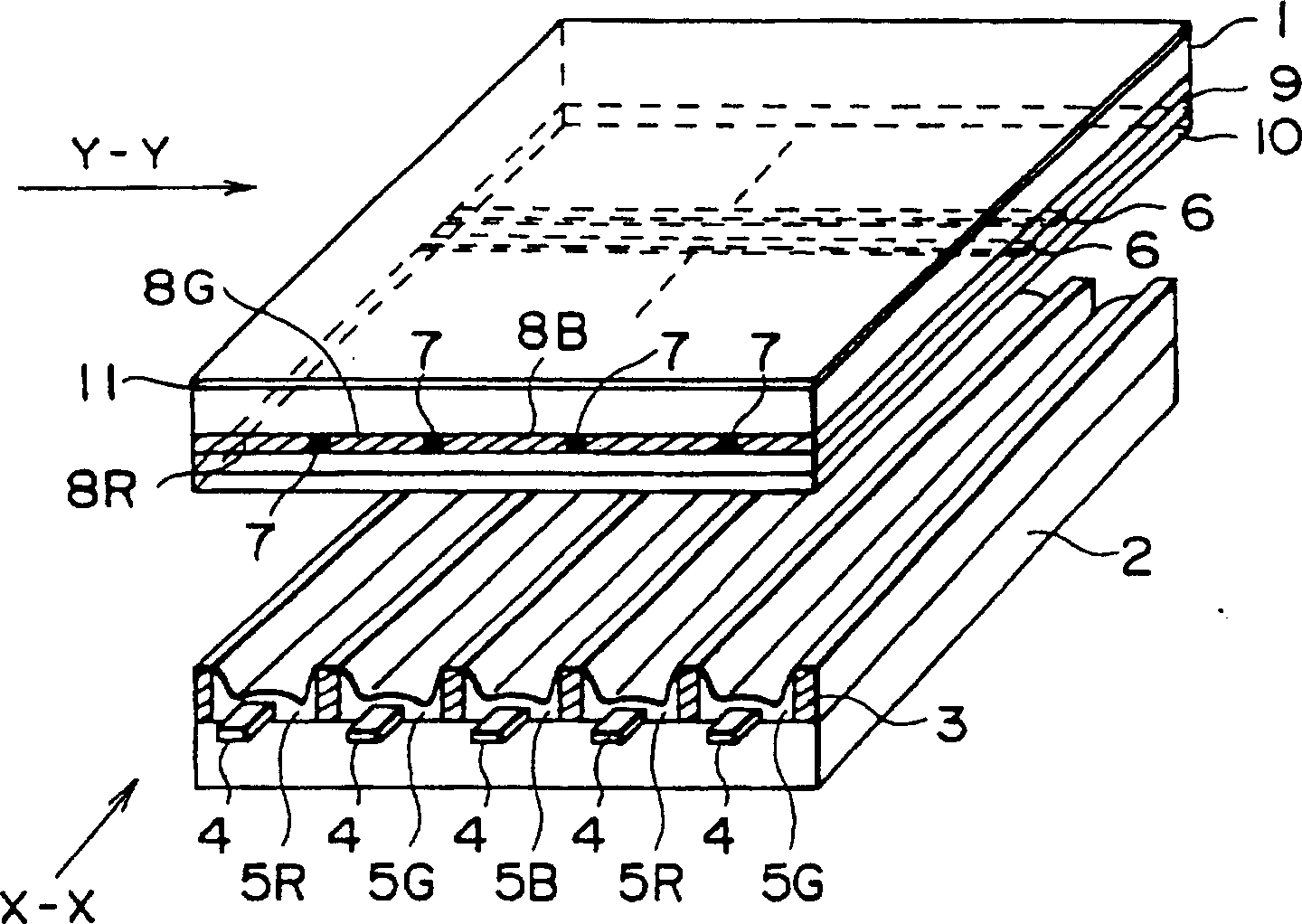
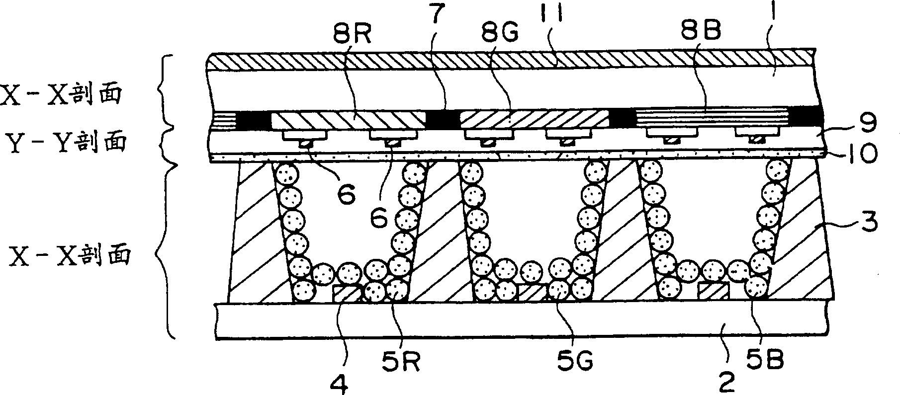
[0026] figure 1 is a perspective view of the entire human structure of an embodiment of the plasma display panel of the present invention, figure 2 yes figure 1 An enlarged view of a partial cutaway of a plasma display panel. Number 1 indicates the front glass substrate (front plate), 2 is the rear glass substrate (rear plate), 3 is the barrier rib, 4 is the address electrode, 5R, 5G and 5B are fluorescent substances, 6 is the support electrode, and 7 is the black matrix , 8R, 8G, 8B are color filters, 9 is an insulating layer, 10 is a protective layer, and 11 is a band selection filter.

[0027] from figure 1 with figure 2 It can be seen from the embodiment that the plasma display panel has such a structure: the front glass substrate 1 and the rear glass substrate 2 are arranged facing each other, and barrier ribs 3 are placed between the two ...


PUM


Abstract

To achieve an expansion of color reproducibility and an improvement in contrast ratio, color filters 8R, 8G and 8B formed in stripes are successively arranged on one surface of a front glass substrate 1, interposing a black matrixes 7 between them. Sustaining electrodes 6 are provided thereon and a dielectric layer 9 and a protecting layer 10 are provided. On a rear glass substrate 2, barrier ribs 3 are provided in the manner they face the respective black matrixes 7, and thus the spaces between the barrier ribs 3 facing the respective color filters 8R, 8G and 8B form cells. The cells are respectively provided with the sustaining electrodes 6 falling at right angles with the address electrodes 4, coated with fluorescent substances 5R, 5G and 5B corresponding to the respective colors, and also sealed to hold discharge gas therein. A wave band selecting filter 11 for screening the light emitted from the discharge gas in the respective cells is provided on the other surface of the front glass substrate 1.

Description

technical field [0001] The present invention relates to a plasma display used as various thin display panels, and more particularly, to a plasma display panel that uses ultraviolet light energy to activate phosphors to generate visible light. Background technique [0002] Plasma display panels (PDPs), which can be manufactured so that their thicknesses are significantly smaller than those of cathode ray tube direct-view display units and rear projection display units, have been viewed as the most promising device for realizing wall-mounted large-screen televisions in the future. At present, however, such plasma display panels are still at a lower level of development than current display components in terms of contrast and brightness. In order for plasma display panels to be widely used in the future, significant improvements must be made to their existing properties. [0003] Under these circumstances, as measures for improving the contrast ratio and color purity of plasma...

Claims


Application Information

Patent Timeline
Patent Type & Authority Patents(China)
IPC IPC(8): H01J11/12H01J11/22H01J11/24H01J11/26H01J11/34H01J11/36H01J11/44H01J11/50
CPCH01J11/44H01J2211/444H01J11/12
Inventor 大泽敦夫大泽通孝石垣正治谷津田则夫佐佐木孝
Owner HITACHI LTD
Why Eureka
Try Eureka