Portable direct-current charging pile detector

A technology of a DC charging pile and a detector, which is applied to the parts, instruments, measuring electricity and other directions of electrical measuring instruments, can solve the problems of simple structure of the heat dissipation device, can not achieve heat dissipation, power failure, etc., and achieve the effect of accelerating heat dissipation and vibration. The effect of reducing the effect and increasing the air velocity

Inactive Publication Date: 2019-05-21
ANHUI NENGTONG NEW ENERGY TECH CO LTD
View PDF20 Cites 1 Cited by
  • Summary
  • Abstract
  • Description
  • Claims
  • Application Information

AI Technical Summary

Problems solved by technology

[0003] The traditional DC charging pile detector, in order to make the operation and portability convenient, will place the body of the AC charging pile detector in a portable box and seal it through the box cover, but the existing storage box has the following disadvantages: (1) due to the The shock absorption protection measures in the body are relatively simple. When vibration occurs, it cannot play a good shock absorption effect, which will easily damage the electrical components inside the DC charging pile detector body; (2) the existing DC charging pile detection Due to the simple structure of the cooling device, the portable box of the instrument cannot achieve the effect of rapid heat dissipation, which often leads to overheating protection and power failure of the DC charging pile detector when the maximum working efficiency is not reached, thereby reducing the working effect; (3) The existing heat dissipation device requires human control, so it is easy to forget to open the heat dissipation device due to subjective reasons, so it will not achieve the effect of heat dissipation. Therefore, we propose a portable detector for DC charging piles

Method used


Image

  • Portable direct-current charging pile detector
  • Portable direct-current charging pile detector
  • Portable direct-current charging pile detector

Examples


Embodiment Construction

[0027] The technical solutions in the embodiments of the present invention will be clearly and completely described below in conjunction with the accompanying drawings in the embodiments of the present invention. Obviously, the described embodiments are only a part of the embodiments of the present invention, rather than all the embodiments. Based on the embodiments of the present invention, all other embodiments obtained by those of ordinary skill in the art without creative work shall fall within the protection scope of the present invention.

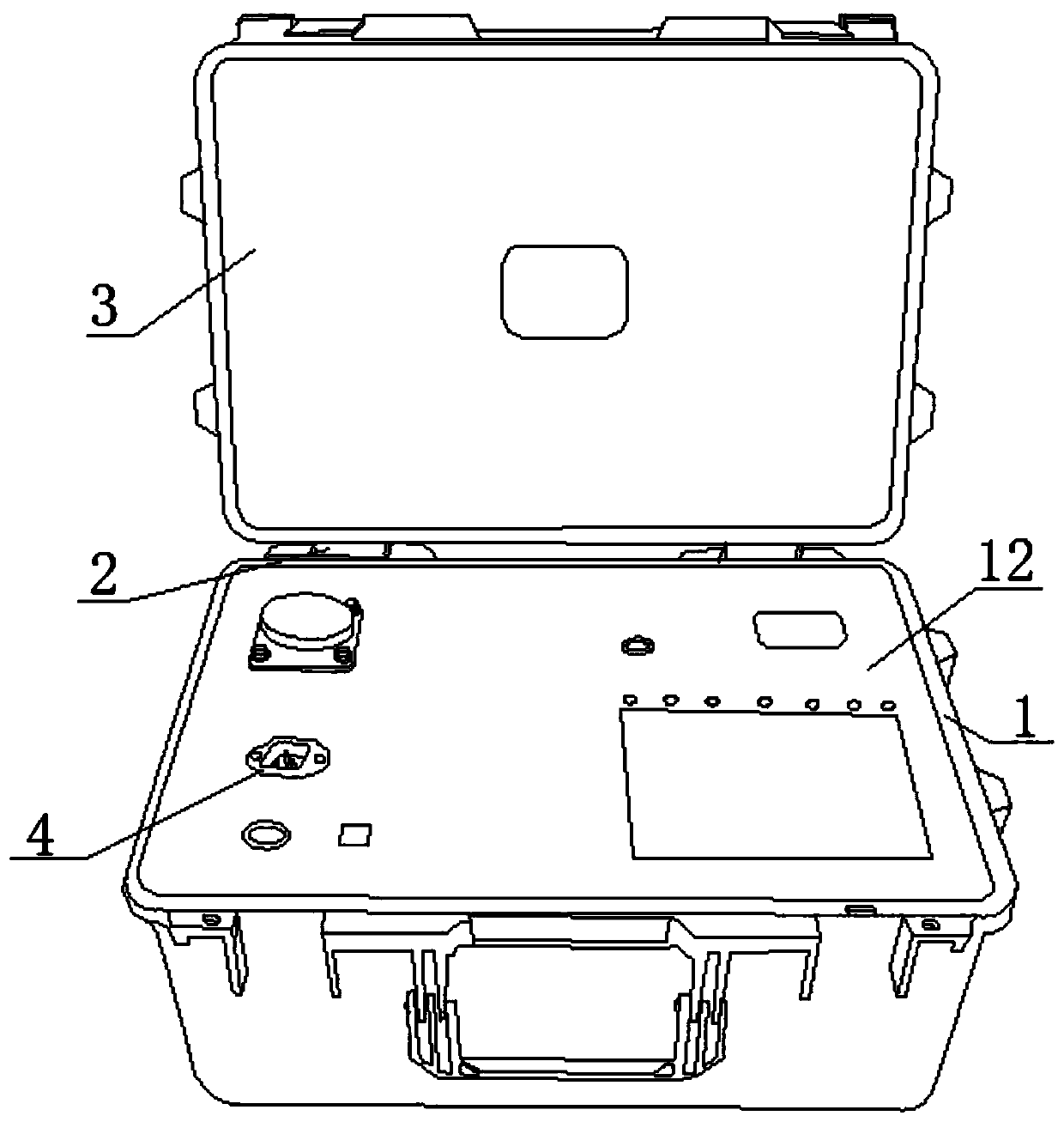
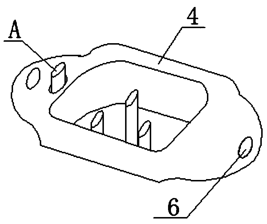
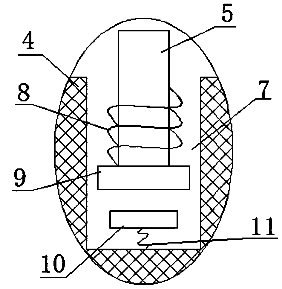
[0028] Please refer to Figure 1 to 7 , A portable DC charging pile detector provided by an embodiment of the present invention includes a box body 1, the upper end of the box body 1 is hinged with a box cover 3 through a plurality of hinges 2, and a DC charging pile detector body is placed in the box body 1. 12. The DC charging pile detector body 12 is provided with a jack assembly 4, and the jack assembly 4 is provided with a control d...


PUM


Abstract

The invention discloses a portable direct-current charging pile detector, which comprises a box body. The upper end of the box body is hinged with a box cover through a plurality of hinges. A direct-current charging pile detector body is arranged in the box body; and an insertion hole assembly is arranged at the direct-current charging pile detector body and is provided with a control device A anda plurality of fixing holes. A support plate is abutted against and is connected with the lower end of the direct-current charging pile detector body. According to the invention, because of the control device A, a cooling device starts to work instantly when an external wire is inserted into the insertion hole assembly, so that a phenomenon of forgetting turning on of the cooling device is avoided. With a damping device, the good damping effect is good; and thus when vibration occurs, the vibration effect is reduced by the effect of the damping device, so that a phenomenon that the electricalcomponents inside the detector body vibrate seriously and thus are damaged is avoided.

Description

Technical field [0001] The invention relates to the technical field of charging pile detectors, in particular to a direct current charging pile portable detector. Background technique [0002] Charging pile detector is a detector that displays voltage and current values. Main function: According to the performance parameter test requirements, the corresponding power can be set through the operation panel, and the discharge power can be set in any combination. Three-phase split-phase independent control; the whole machine adopts electronic circuit control, and has the function of automatic overheating protection: when overheating occurs due to special reasons, the load can be automatically cut off. Display voltage, current value, power factor of each phase, frequency, active power of each phase, etc. The data storage function can be realized through the PC. The power input adopts a segmented method. The load adopts energy consumption mode, and the heat dissipation adopts forced...

Claims


Application Information

Patent Timeline
Patent Type & Authority Applications(China)
IPC IPC(8): G01R31/00G01R1/02
Inventor 陶旭何仕玉张文飞
Owner ANHUI NENGTONG NEW ENERGY TECH CO LTD
Why Eureka
Try Eureka