Crossing traffic flow monitoring system

A technology of traffic flow and monitoring system, which is applied in traffic control system, road vehicle traffic control system, traffic flow detection, etc. It can solve problems such as low work efficiency, congestion, and inability to analyze and process data, so as to achieve simple installation and avoid road traffic. Congestion, the effect of rationally arranging human resources

Inactive Publication Date: 2019-05-21
魏一凡
View PDF6 Cites 4 Cited by
  • Summary
  • Abstract
  • Description
  • Claims
  • Application Information

AI Technical Summary

Problems solved by technology

[0003] At present, the main way to solve these problems is to invest in building road facilities, but because the cost is getting higher and higher, it is unsustainable, and the monitoring of road traffic conditions has become an important task of the traffic control department; On the one hand, the cost of road widening is high, and the cost of land in the city is very high, and the occupation of land resources is a greater cost. On the other hand, for the old city, the road cannot be renovated or widened; therefore, through reasonable control of traffic flow, guide the congestion area to solve the technical problem of urban congestion
[0004] The existing monitoring system needs cameras to monitor the intersections, which cannot accurately judge the traffic flow, and requires staff to monitor in real time. While the work efficiency is low, the measured data cannot be analyzed and processed; some use geomagnetism Coils, etc. use magnetic field technology to monitor traffic flow. If the magnetic field is turned on for a long time, it will generate a large amount of electromagnetic radiation to the surrounding people or the environment, endangering the safety of drivers.

Method used


Image

  • Crossing traffic flow monitoring system
  • Crossing traffic flow monitoring system
  • Crossing traffic flow monitoring system

Examples


Embodiment Construction

[0037] In order to make the purpose, features and advantages of the present invention more obvious and understandable, the technical solutions in the embodiments of the present invention will be clearly and completely described below in conjunction with the accompanying drawings in the embodiments of the present invention. Obviously, the described The embodiments are only some of the embodiments of the present invention, but not all of them. Based on the embodiments of the present invention, all other embodiments obtained by those skilled in the art without making creative efforts belong to the protection scope of the present invention.

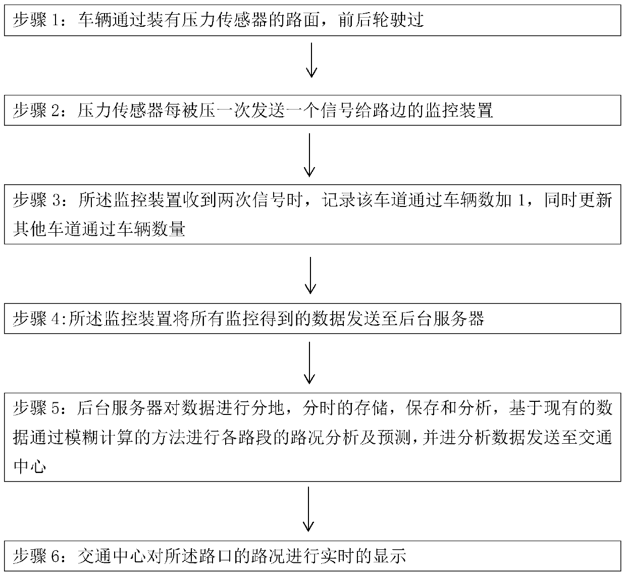
[0038] Specifically, such as figure 1 As shown, the invention provides a kind of crossroad traffic flow monitoring method, described method comprises the following steps:

[0039] S1: The vehicle passes through the road equipped with pressure sensors, and the front and rear wheels pass by; each time the pressure sensor is pressed, a signal i...


PUM


Abstract

The invention discloses a crossing traffic flow monitoring system which relates to the field of traffic flow monitoring. The crossing traffic flow monitoring system comprises a pressure sensor, a monitoring device, an A / D signal converter and a microprocessor. The pressure sensor is arranged at an area below a crossing channel and is used for monitoring the number of vehicles on the road. The pressure sensor transmits one signal to a roadside monitoring device when the pressure sensor is pressed once. When the monitoring device receives two signals, the monitoring device adds one to the numberof passing vehicles and simultaneously updates the number of passing vehicles in other lanes. The monitoring device transmits all monitored data to a background server. The background server performsposition-specified and position-specified storage and analysis on data, performs road condition analysis and predication on each road segment based on existing data through a fuzzy calculating method, and transmits analysis data to a traffic center. The crossing traffic monitoring system can supply pollution-free traffic flow detection and furthermore performs fuzzy calculation processing on themeasured traffic flow, thereby preventing a traffic jam.

Description

technical field [0001] The invention relates to the field of traffic flow monitoring, in particular to a crossroad traffic flow monitoring system. Background technique [0002] With the development of human economy and society, automobiles play a pivotal role in people's lives as a means of transportation. While it brings great convenience to human beings, it also makes people face many challenges such as traffic congestion and road safety problems during driving. [0003] At present, the main way to solve these problems is to invest in road facilities, but because the cost is getting higher and higher, it is unsustainable, and the monitoring of road traffic conditions has become an important task of the traffic control department; On the one hand, the cost of road widening is high, and the cost of land in the city is very high, and the occupation of land resources is a greater cost. On the other hand, for the old city, the road cannot be reconstructed or widened; therefore,...

Claims


Application Information

Patent Timeline
Patent Type & Authority Applications(China)
IPC IPC(8): G08G1/01G08G1/02G08G1/065
Inventor 魏一凡
Owner 魏一凡
Why Eureka
Try Eureka