
Self-closing electronic charging equipment and use method thereof

A charging device and self-closing technology, which is applied in the field of self-closing electronic charging equipment, can solve problems such as large volume and weight, damage to charging equipment, and affecting charging efficiency, so as to reduce the incidence of short circuits, reduce maintenance costs, Reduce the effect of poor contact

Active Publication Date: 2019-05-21
SHAANXI SCI TECH UNIV
View PDF4 Cites 0 Cited by
  • Summary
  • Abstract
  • Description
  • Claims
  • Application Information

AI Technical Summary

Problems solved by technology

[0004] However, when the existing mobile charging equipment is in use, there is usually such a contradiction. When the power is large, the volume and weight will inevitably be large, which is not easy to carry. When the volume and weight are small, the power cannot meet people's needs. Moreover, mobile charging equipment with large power will be very cumbersome for short-distance travel due to its weight and volume, while mobile charging equipment with small power can hardly meet the demand for long-distance travel. Type mobile charging equipment, but the connection points of the various components of the combined mobile charging equipment will generate heat. Under normal circumstances, heat generation has little effect on charging, but excessive heat generation will lead to short circuit, and in serious cases will not only lead to charging If the device is damaged, it will even damage the electronic device being charged. At the same time, after multiple combinations and disassembly, the terminal part will become loose, resulting in poor contact, affecting charging efficiency, and there are certain safety hazards

Method used


Image

  • Self-closing electronic charging equipment and use method thereof
  • Self-closing electronic charging equipment and use method thereof
  • Self-closing electronic charging equipment and use method thereof

Examples


Embodiment 1

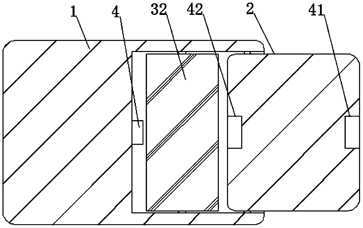
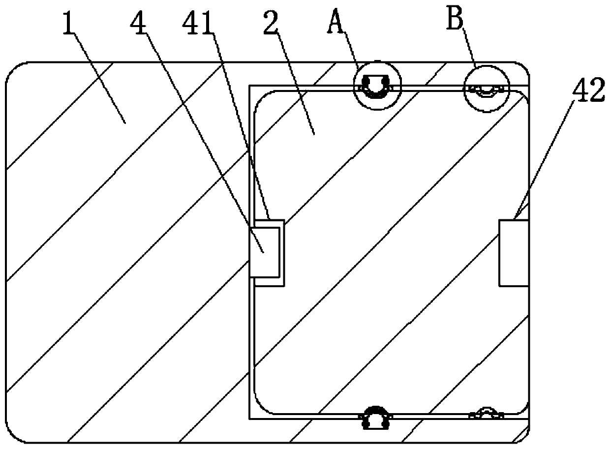
[0058] See figure 1 , A self-closing electronic charging device, comprising a female charging body 1 and a sub-charging body 2. The left and right ends of the sub-charging body 2 are electrically connected with an inner charging port 42 and an outer charging port 41, respectively. The female charging body 1 There is a dual-purpose slot excavated inside. The dual-purpose slot is equipped with an external battery 3. The dual-purpose slot is matched with the sub-type charging body 2, and the external battery 3 is electrically connected to the female charging body 1 through the inner terminal 81. The dual-purpose slot A positioning column 4 is fixedly connected to the left inner wall, and the outer charging port 41 and the inner charging port 42 are matched with the positioning column 4, please refer to image 3 When the female charging body 1 and the sub-charging body 2 are used in combination, the sub-charging body 2 is located in the female charging body 1. At this time, the posit...


PUM


Abstract

The invention discloses self-closing electronic charging equipment, and a use method thereof, and belongs to the field of the charging equipment. The self-closing electronic charging equipment comprises a linkage contact-assisting ring; when the mobile charging equipment is used in a combined manner, the linkage contact-assisting ring is extruded, an air location in a linkage cavity is transferred, so that the contact of the linkage contact-assisting ring becomes face contact from point contact, a clamping effect is formed on a binding post, and the binding post is located in a balance state;the binding post is hard to loosen, and the binding post can be located in a contact state to maintain the balance in the use when the binding post is loosened, thereby reducing the occurrence rate ofthe bad contact caused by the loosening of the binding post. Furthermore, the heat-conducting silica gel material at the external of the linkage contact-assisting ring and the copper plate in the internal thereof can transfer the heat produced on the binding post to a location far away from the binding post in the use process of the mobile charging equipment, thereby reducing the occurrence rateof the short-circuit phenomenon due to overheat at the joint part.

Description

Technical field [0001] The invention relates to the field of charging equipment, and more specifically, to a self-closing electronic charging equipment and a method of use thereof. Background technique [0002] With the development of communication technology, various portable electronic devices are widely used, such as portable computers, tablet computers, smart phones, and portable multimedia players. To enhance portability, these portable electronic devices are usually powered by batteries. However, the battery capacity for powering portable electronic devices is limited. When the battery energy is exhausted, it is necessary to charge the battery immediately, replace the battery of the portable electronic device, or supply power to the portable electronic device from other external devices to make the portable electronic device Able to continue working. [0003] In order to adapt to the use of mobile electronic devices, especially to adapt to the use of digital products such a...

Claims


Application Information

Patent Timeline
IPC IPC(8): H02J7/00
CPCY02E60/10
Inventor 郑争兵
Owner SHAANXI SCI TECH UNIV
Learn More