Linear motor physical precision compensation control system and method

A linear motor, compensation control technology, applied in control system, AC motor control, motor parameter estimation/correction, etc., can solve the problem of physical position deviation, poor physical accuracy, and deviation between the feedback data of the grating scale and the actual position and other issues to achieve precision optimization and improve the effect of displacement control precision

Inactive Publication Date: 2019-05-21
SHENZHEN VMMORE CONTROL TECH
View PDF7 Cites 6 Cited by
  • Summary
  • Abstract
  • Description
  • Claims
  • Application Information

AI Technical Summary

Problems solved by technology

[0003] However, in the above-mentioned prior art, there are the following problems: the invention patent application with the publication number CN1897453A is mainly aimed at performing feed-forward compensation for the nonlinear torque brought by the motor body and mechanical parts, which can improve the stability of the running speed curve to a certain extent There is nothing to do when there is a deviation between the feedback data of the grating ruler and the actual position
In addition, during the installation process of the grating ruler, due to factors such as the flatness of the installation surface, the installation level of the grating ruler and the guide rail, and even the physical accuracy of the grating ruler itself, the position represented by the feedback data of the grating ruler and the actual physical position will appear. Deviation, and the drive can only be controlled based on the data of the grating scale, so the actual physical accuracy is not good

Method used


Image

  • Linear motor physical precision compensation control system and method
  • Linear motor physical precision compensation control system and method
  • Linear motor physical precision compensation control system and method

Examples


Embodiment Construction

[0023] The present invention will be described in more detail below in conjunction with the accompanying drawings and embodiments.

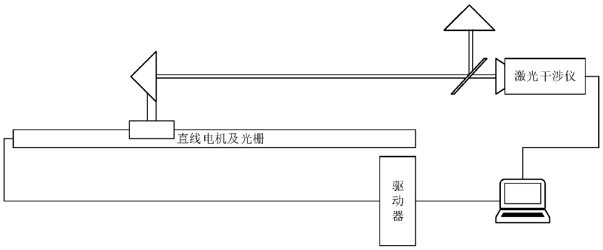
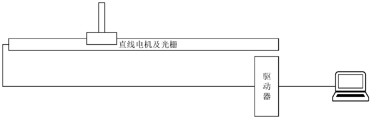
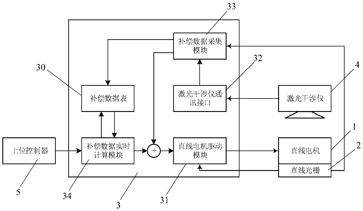
[0024] The invention discloses a linear motor physical precision compensation control system, which combines Figure 1 to Figure 3 As shown, it includes:

[0025] linear motor 1;

[0026] a linear grating ruler 2, used to collect the linear displacement of the linear motor 1;

[0027] Main control unit 3, the linear motor 1 and the linear grating ruler 2 are respectively electrically connected to the main control unit 3, the main control unit 3 is preset with a compensation data table 30, and the moving track of the linear motor 1 is preset There are multiple collection points, and the main control unit 3 is used to execute:

[0028] During the calibration learning process, when the linear motor 1 moves to each collection point, the position data collected by the linear grating scale 2 is fed back to the main control unit 3 and stored in the c...


PUM


Abstract

The invention discloses a linear motor physical precision compensation control system. The linear motor physical precision compensation control system comprises a linear motor, a linear grating ruler,and a main control unit, wherein the linear motor and the linear grating ruler are electrically connected to the main control unit separately; a compensation data table is pre-arranged in the main control unit, and a plurality of collection points are pre-arranged on the moving track of the linear motor; the main control unit is used for executing a calibration and learning process, wherein whenthe linear motor moves to each collection point, the position data acquired by the linear grating ruler is fed back to the main control unit and is stored in the compensation data table; and meanwhile, the main control unit is used for executing an operation control process, wherein the main control unit determines a collection point according to the target position sent by an upper controller, inquires the position data of the linear grating ruler corresponding to the collection point in the compensation data table, and then controls the linear motor to run to the collection point according to the position data of the linear grating ruler so as to further arrive at the target position. According to the control system, the feedback data of the linear grating ruler can be compensated, so that the displacement control precision of the linear motor is further improved.

Description

technical field [0001] The invention relates to a motor precision control system, in particular to a linear motor physical precision compensation control system and method. Background technique [0002] Linear motor is a high-speed, high-precision linear motion motor, which generally reciprocates in a fixed linear range, and uses a linear grating scale as position feedback. The linear motor mover is directly connected to the load, and the driver measures the actual load position completely according to the feedback of the grating scale. Therefore, the accuracy of the entire control system mainly depends on the accuracy of the grating scale. In the prior art, the Chinese invention patent application with the publication number CN1897453A discloses a method for improving the motion precision of a permanent magnet linear motor, and introduces a method for improving the motion precision of a linear motor through feedforward. By conducting a trial run before the actual operation...

Claims


Application Information

Patent Timeline
Patent Type & Authority Applications(China)
IPC IPC(8): H02P23/14H02P25/06
Inventor 刘好川陈阳
Owner SHENZHEN VMMORE CONTROL TECH
Why Eureka
Try Eureka