
Handle unit

A technology of components and receiving parts, applied in the field of grasping units, can solve problems such as damage, achieve the effects of reducing complexity, simple and reliable connection, and improving configuration possibilities

Pending Publication Date: 2019-05-21
WANZL GMBH & CO KGAA
View PDF11 Cites 0 Cited by
  • Summary
  • Abstract
  • Description
  • Claims
  • Application Information

AI Technical Summary

Problems solved by technology

[0006] Due to the increased force generated by the protruding grip parts, damage can occur in the sliding handle units mentioned in the prior art, especially if they are used incorrectly

Method used


Image

  • Handle unit
  • Handle unit
  • Handle unit

Examples


Embodiment Construction

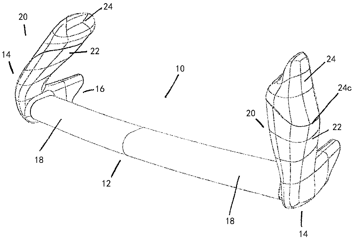
[0036] figure 1 An exemplary embodiment of the handle unit 20 according to the invention for moving the handle unit 10 is shown in perspective.

[0037] The sliding handle unit 10 has a cross brace 12 , which is here embodied as a transverse rod.

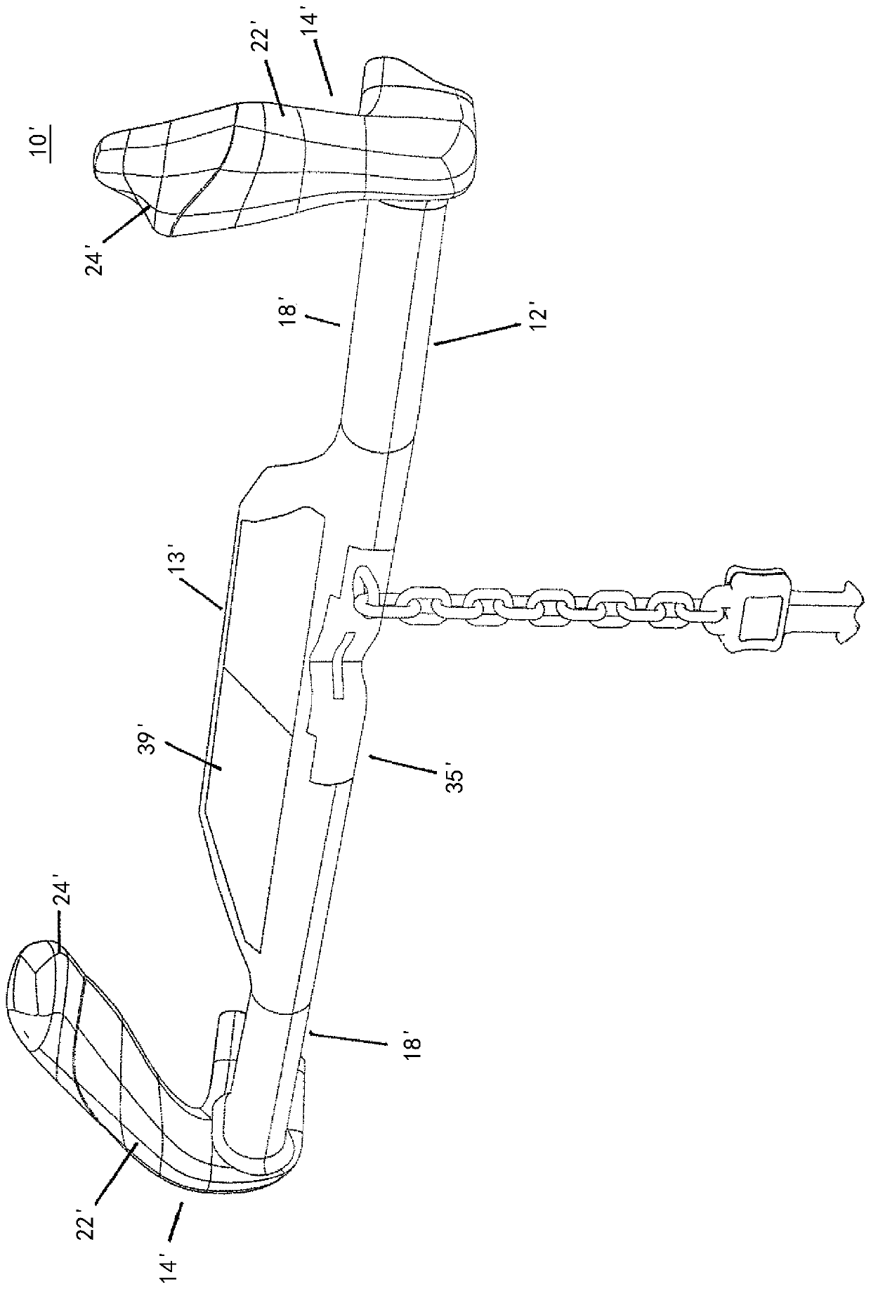
[0038] However, the cross brace 12 can also have a central part 13' and two gripping sections 18' separated from each other by the central part 13' (see image 3 ).

[0039] However, the cross brace 12 can also have a coin deposit system, as disclosed for example in EP 0 985 200 B1.

[0040] Such as figure 1 As shown, in the assembled state, the sliding handle unit 10 furthermore has an end part 14 at each end of the cross strut 12 , which are configured identically to each other in a mirror-inverted manner.

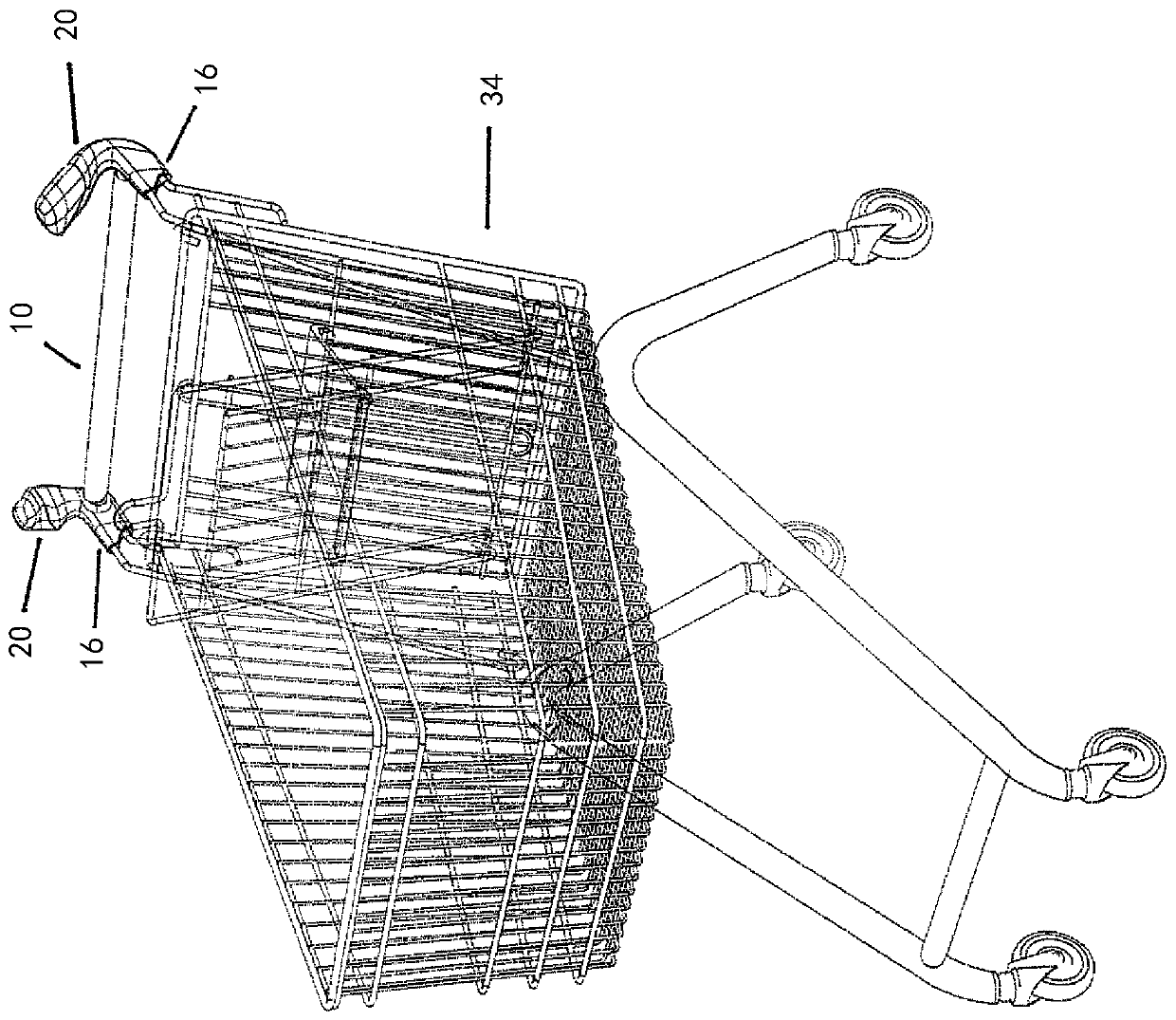
[0041] The end piece 14 has a fixing device 16 for fixing the end piece 14 on a manually movable transport trolley 34 (see figure 2 ).

[0042] Such a transport trolley 34 can be a shopping cart or a transport trolley for...


PUM


Abstract

The present invention relates to a gripping unit (20) for a push handle unit (10) of a trolley (34) which is movable by hand, wherein the gripping unit (20) in each case consists at least of a gripping unit receptacle (22) and a gripping unit insert (24), which together in the mounted state form a handle horn (26), which protrudes in a free-standing manner, for the push handle unit (10),and wherein a fastening device (16) is integrally formed on each gripping unit receptacle (22) and serves for the fastening to the trolley (34), wherein the gripping unit receptacle (22) and the gripping unit insert (24) are connected to each other in the mounted state by means of at least one tongue and groove connection (28).

Description

technical field [0001] The invention relates to a gripping unit for a push-handle unit of a manually movable transport vehicle, wherein the gripping unit consists of at least a gripping unit receptacle and a gripping unit insert, the gripping unit receiving In the assembled state, the part and the grip unit insert together form a suspended upwardly protruding grip horn for displacing the handle unit. Background technique [0002] Transport trolleys for heavy and bulky goods, such as are found in building materials markets or mass markets, are often provided with protruding grips. These grips allow for a more natural or ergonomic handling when moving the loaded transporter. [0003] Furthermore, protruding grips for a more ergonomic handling have also been used on transport carts in retail operations, said grips being typically arranged on the ends of horizontally extending transverse bars. [0004] WO 2012 / 042033 A1 discloses a push handle for transport vehicles, which, in...

Claims


Application Information

Patent Timeline
Patent Type & Authority Applications(China)
IPC IPC(8): B62B5/06B62B3/14
CPCB62B3/1416B62B3/1424B62B3/1428B62B3/1472B62B5/06B62B2202/023
Inventor D·施特克勒
Owner WANZL GMBH & CO KGAA
Learn More