Cross-flow blower and indoor unit of air-conditioning device equipped with same
A cross-flow and fan technology, which is applied to components of pumping devices for elastic fluids, air-conditioning systems, machines/engines, etc., can solve problems such as reduction and increase in pressure loss, and achieve the effects of suppressing noise and suppressing surge Effect
- Summary
- Abstract
- Description
- Claims
- Application Information
AI Technical Summary
Problems solved by technology
Method used
Image

Examples
no. 1 approach 》
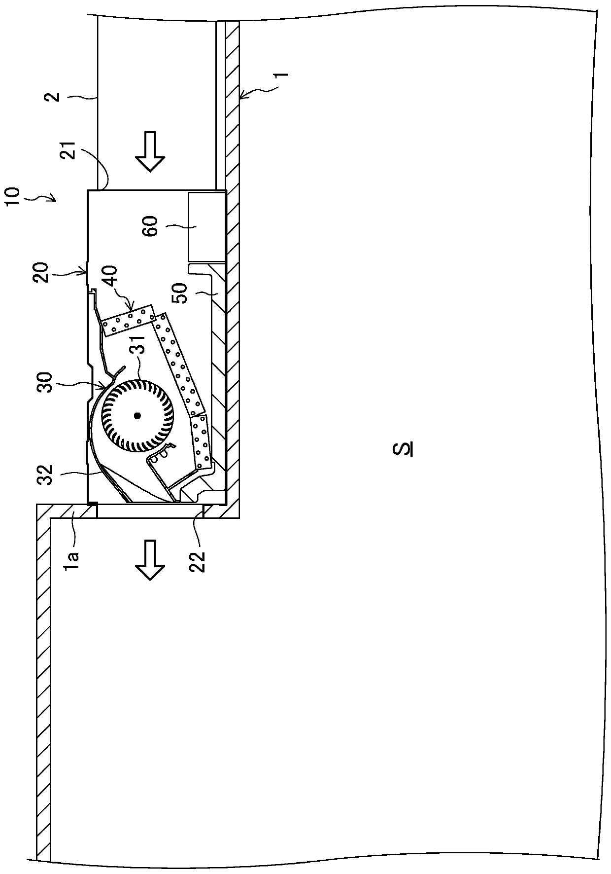
[0046] Such as figure 1 As shown, the indoor unit 10 is installed in a suspended ceiling 1 formed by making the ceiling of the indoor space S protrude a little toward the room. The indoor unit 10 includes a casing 20 , a cross-flow fan 30 , a heat exchanger 40 , a water tray 50 and an electronic component box 60 . The cross-flow fan 30 , the heat exchanger 40 , the water receiving tray 50 and the electronic component box 60 are arranged in the casing 20 .
[0047] The cabinet 20 is formed of a substantially rectangular parallelepiped box. Specifically, in figure 1 Among them, the casing 20 is configured as a thin box with a long vertical length, and the vertical length (front and back direction of the paper) is longer than the horizontal (left and right direction of the paper) length of the box when viewed from above, and the height is smaller than the horizontal length. On one lateral side of the casing 20 ( figure 1 An inflow port 21 is formed on the right side of the ho...
no. 2 approach 》
[0101] In the second embodiment, the ceiling-mounted indoor unit 10 in the first embodiment is configured as a wall-mounted indoor unit 10 mounted on a wall.
[0102] Specifically, as Figure 9 As shown, the indoor unit 10 includes a casing 20 , a cross-flow fan 30 , a heat exchanger 40 , a water tray 50 and a filter 80 . It should be noted that the indoor unit 10 further includes a control unit not shown. The fan 30 , the heat exchanger 40 , the water receiving tray 50 , the filter 80 and the control unit are arranged in the casing 20 .
[0103] The cabinet 20 is formed into a box shape by a front panel 20F covering the front surface, a rear panel 20R covering the rear surface, an upper panel 20U covering the upper surface, a bottom panel 20B covering the bottom surface, and two side panels 20S covering both sides. . In addition, an inlet 21 through which air flows in and an outlet 22 through which air flows out are formed in the casing 20 . The inflow port 21 is formed o...
no. 3 approach 》
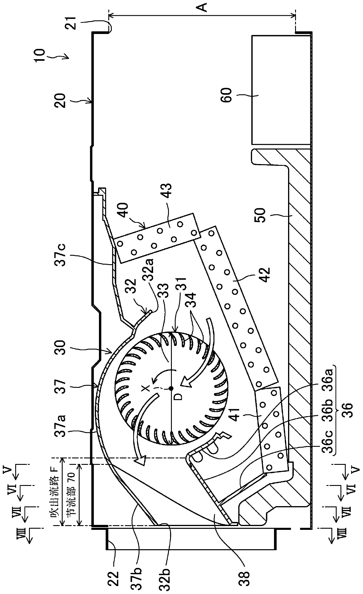
[0149] The third embodiment is obtained by changing the shape of the blowing flow path F of the first embodiment. Except for the shape of the blowing flow path F, the configuration is the same as that of the first embodiment. Hereinafter, only the structure of the blowing flow path F and the flow of air in the blowing flow path F that are different from those of the first embodiment will be described, and descriptions of other structures and operations will be omitted.
[0150] [Blowout flow path]
[0151] Such as Figure 14 As shown, in this third embodiment, the first extension wall portion (first wall portion) 36b of the first guide member 36 and the second extension wall portion (first wall portion) of the second guide member 37 arranged to face each other are also formed. The second wall portion) 37b and the two side wall portions 38 define the blowing flow path F. In addition, the outlet flow path F has a throttle portion 70 in which the flow path cross-sectional area...
PUM
 Abstract
Description
Claims
Application Information
 - R&D
- Intellectual Property
- Life Sciences
- Materials
- Tech Scout
- Unparalleled Data Quality
- Higher Quality Content
- 60% Fewer Hallucinations
Browse by: Latest US Patents, China's latest patents, Technical Efficacy Thesaurus, Application Domain, Technology Topic, Popular Technical Reports.
© 2025 PatSnap. All rights reserved.Legal|Privacy policy|Modern Slavery Act Transparency Statement|Sitemap|About US| Contact US: help@patsnap.com