Range hood

A technology of range hood and motor is applied in the fields of removing oil fume, household heating, space heating and ventilation details. Effect

Active Publication Date: 2019-05-21
FUJI IND
View PDF8 Cites 0 Cited by
  • Summary
  • Abstract
  • Description
  • Claims
  • Application Information

AI Technical Summary

Problems solved by technology

However, filter replacement work and filter cleaning work are troublesome

Method used


Image

  • Range hood
  • Range hood
  • Range hood

Examples


Embodiment Construction

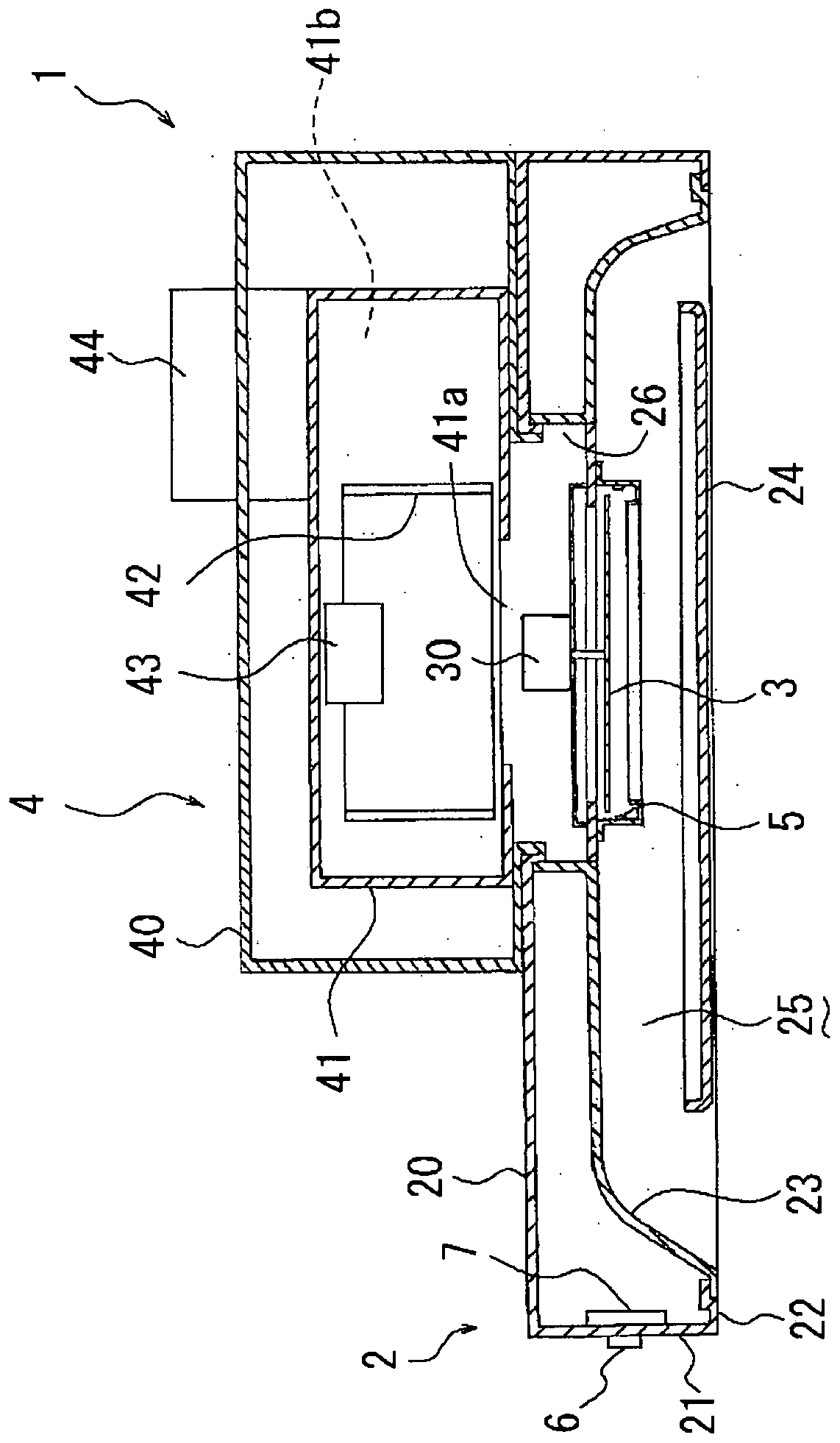
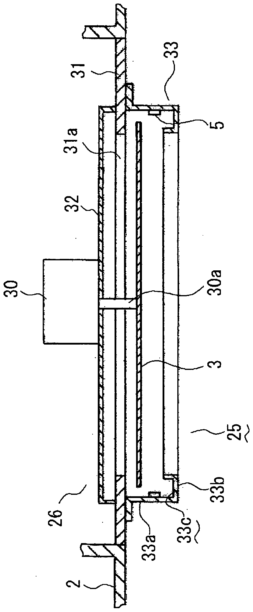
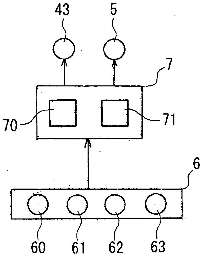
[0037] refer to figure 1 , figure 2 and image 3 The first embodiment of the present invention will be described.

[0038] figure 1 is a sectional view of the range hood, figure 2 It is an enlarged view of the filter attachment part, image 3 It is an explanatory diagram of the operation operation unit and the control unit.

[0039] The range hood 1 includes a cover 2 , a filter 3 , a blower 4 and an ultraviolet light source 5 .

[0040] The cover 2 is formed in a low rectangular box shape with a top panel 20 , a peripheral panel 21 and a lower panel 22 . The lower surface plate 22 has a recessed portion 23 recessed toward the top plate 20 , and a rectifying plate 24 is mounted in the recessed portion 23 , and a flow path 25 is formed by the rectifying plate 24 and the recessed portion 23 . The lower portion of the flow path 25 is opened to the lower side of the cover 2 , and the upper portion of the flow path 25 is opened to the upper side of the cover 2 through the ...


PUM


Abstract

The purpose of the invention is to provide a range hood that can efficiently emit ultraviolet light to a filter regardless of oil smoke or the like flowing in the hood, that prevents people in the room from experiencing bad odors, and that does not allow ozone to fill a room. A range hood comprises a hood (2), a filter (3), a blower (4) that rotates a fan (42) with a fan motor (43), an ultravioletlight source (5) that emits ultraviolet light on the filter (3), and a control unit (7) that controls the fan motor (43) and the ultraviolet light source (5). The control unit (7) illuminates the ultraviolet light source (5) for a set time after stopping operation from an operating state and simultaneously rotates the fan (42) while the ultraviolet light is being emitted by driving the fan motor(43) for the set time.

Description

technical field [0001] The present invention relates to a cooker hood which collects and discharges cooking fumes and the like generated during heating and cooking. Background technique [0002] In the past, as a cooker hood, the following range hood is known. That is, the range hood includes a cover, a filter, and a blower. After the filter removes oil from the collected cooking fumes, etc., the cooking fumes and the like are discharged outside the house, etc. [0003] In the range hood as described above, oil adheres to the filter to make the filter dirty, so the dirty filter is replaced with a new filter, or the dirty filter is cleaned. However, filter replacement work and filter cleaning work are troublesome. [0004] Therefore, a range hood has been proposed that irradiates ultraviolet rays to the filter when the blower is driven, that is, when the range hood is in operation, thereby decomposing and removing the oil adhering to the filter (for example, refer to Patent...

Claims


Application Information

Patent Timeline
Patent Type & Authority Applications(China)
IPC IPC(8): F24F7/06B01D46/42F24F7/007F24F13/28F24C15/20
CPCB01D46/42F24F1/00F24F7/007F24F7/06F24F13/28F24C15/20
Inventor 柏村浩介
Owner FUJI IND
Why Eureka
Try Eureka