Check patentability & draft patents in minutes with Patsnap Eureka AI!

Detection device, detection method, and detection program

A detection device and reflected wave technology, which can be used in measuring devices, transportation and packaging, radio wave measurement systems, etc., and can solve problems such as increasing the wave transmission voltage gain

Active Publication Date: 2019-05-21
PANASONIC INTELLECTUAL PROPERTY MANAGEMENT CO LTD
View PDF18 Cites 0 Cited by
  • Summary
  • Abstract
  • Description
  • Claims
  • Application Information

AI Technical Summary

Problems solved by technology

However, when the gain of the transmitted wave voltage is increased, the transmitted wave hits the road and is reflected, and the obstacle detection device erroneously detects that there is an obstacle on the road based on only the reflected wave from the road.

Method used


Image

  • Detection device, detection method, and detection program
  • Detection device, detection method, and detection program
  • Detection device, detection method, and detection program

Examples


Deformed example 1

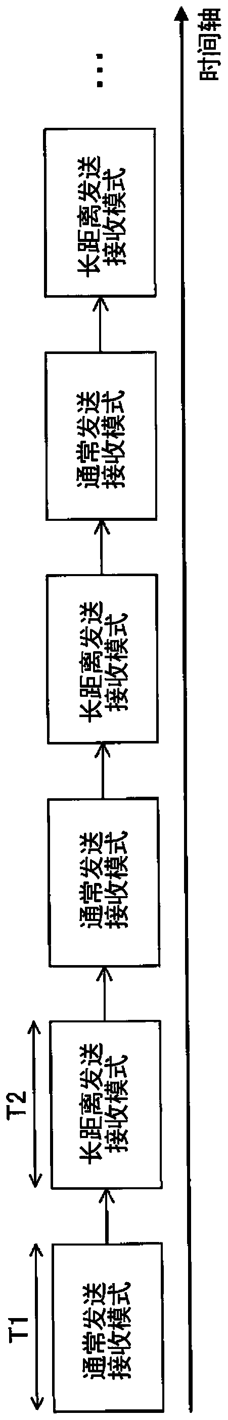
[0083] In the above-mentioned embodiment, the case where the normal transmission / reception mode and the long-distance transmission / reception mode are alternately performed with the same length of unit time has been described as an example, but it is not limited to this.

[0084] For example, the execution time of the long-distance transmission and reception mode may be longer than the execution time of the normal transmission and reception mode. use Picture 9 To illustrate the example. in Picture 9 In, and image 3 Similarly, it is assumed that the unit time T1 and the unit time T2 have the same length.

[0085] Such as Picture 9 As shown, it may also be that the normal transmission and reception mode is executed for the unit time T1, on the contrary, the long-distance transmission and reception mode is executed for a duration of twice the unit time T2.

[0086] According to this modification, the long-distance transmission / reception mode is executed longer than the normal transm...

Deformed example 2

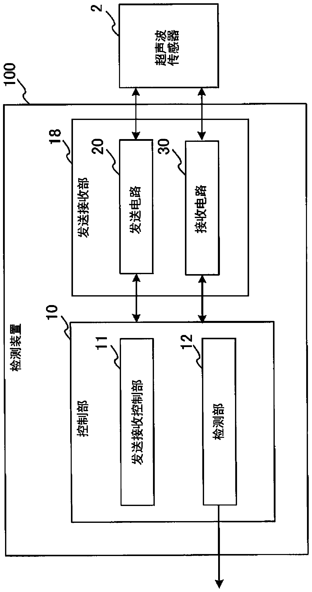
[0088] In the above-mentioned embodiment, for example, when the vehicle speed of the vehicle 1 is equal to or higher than the threshold value, the transmission and reception control unit 11 may output to the transmission circuit 20 and the reception circuit 30 a control signal for instructing to continue the long-distance transmission and reception mode. . In addition, the transmission and reception control unit 11 receives, for example, a vehicle speed sensor (not shown) indicating the vehicle speed of the vehicle 1 (the same applies hereinafter).

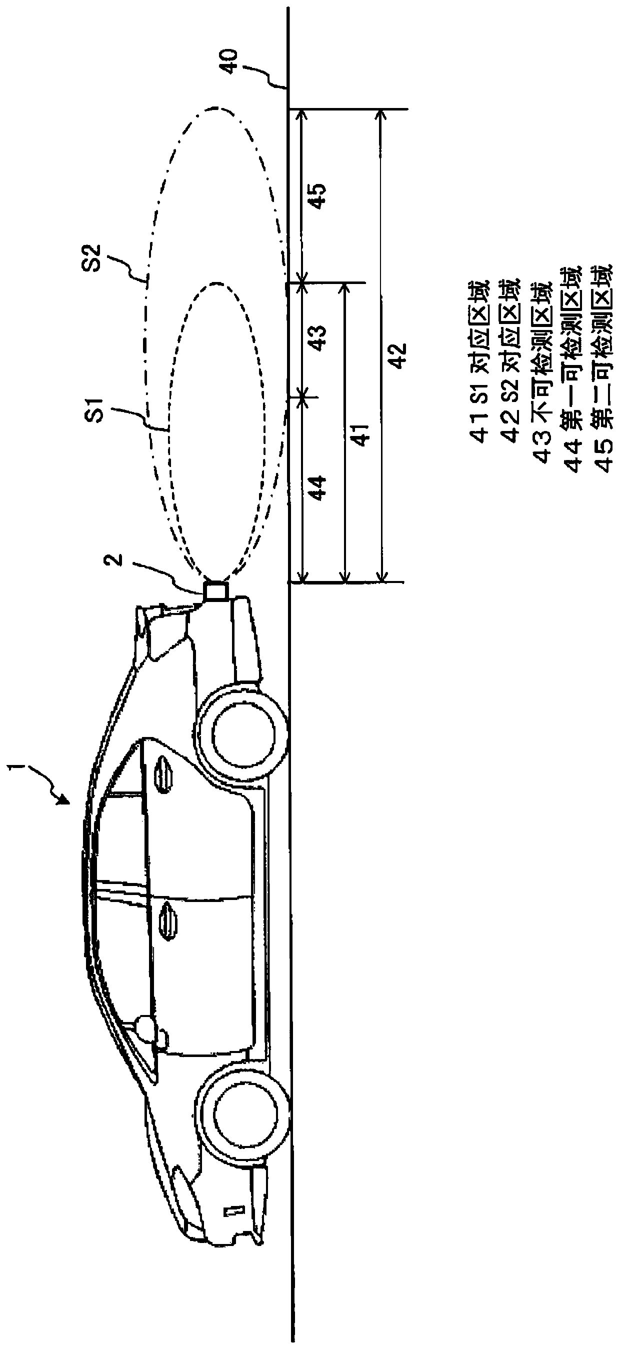
[0089] Or, for example, when the distance between the ultrasonic sensor 2 and the obstacle is greater than or equal to the threshold value, the transmission and reception control unit 11 may output to the transmission circuit 20 and the reception circuit 30 an instruction to continue the long-distance transmission and reception mode. control signal.

[0090] Or, for example, when the speed of the vehicle 1 is greater than or equal to ...


PUM


Abstract

This detection device has a transceiver unit and a detection unit. The transceiver unit: alternately transmits, from an ultrasonic wave sensor used in a vehicle, a first transmission wave that has a first amplitude level and a second transmission wave that has a second amplitude level greater than the first amplitude level; and receives, from the ultrasonic wave sensor, a first reflected wave thatcorresponds to the first transmission wave and a second reflected wave that corresponds to the second transmission wave. The detection unit detects an obstacle on the basis of a first reflected waveor second reflected wave having a reception level greater than a prescribed threshold value. The detection unit detects an obstacle on the basis of a second reflected wave, among second reflected waves, that does not include a second road surface reflected wave.

Description

Technical field [0001] The present disclosure relates to a detection device, a detection method and a detection program for detecting obstacles. Background technique [0002] Conventionally, an obstacle detection device has been known that uses an ultrasonic sensor (sonar) mounted on the rear part of a vehicle such as an automobile to detect an obstacle existing behind the vehicle. The ultrasonic sensor transmits ultrasonic waves (transmitted waves) toward the rear of the vehicle, and the obstacle detection device receives the reflected waves reflected by the ultrasonic waves after encountering obstacles, and detects obstacles based on the reflected waves. [0003] In such an obstacle detection device, in the case of increasing the reach of the transmission wave, it may be considered to increase the transmission wave voltage gain or increase the number of wave transmission pulses. However, when the transmission wave voltage gain is increased, the transmitted wave is reflected on t...

Claims


Application Information

Patent Timeline
Patent Type & Authority Applications(China)
IPC IPC(8): G01S7/524B60R21/00G01S15/93G01S15/931
CPCB60R21/00G01S15/93G01S7/524G01S15/931G01S2015/938G01S7/527G01S15/10G01S15/102G01S15/08
Inventor 小川真也上田孝典山岸龙明
Owner PANASONIC INTELLECTUAL PROPERTY MANAGEMENT CO LTD
Features
  • R&D
  • Intellectual Property
  • Life Sciences
  • Materials
  • Tech Scout
  • Unparalleled Data Quality
  • Higher Quality Content
  • 60% Fewer Hallucinations
Learn More