Optical sensor for distance and/or speed measurement, system for mobility monitoring of autonomous vehicles, and method for mobility monitoring of autonomous vehicles

An optical sensor and speed measurement technology, applied in the field of optical sensors, can solve the problems of indistinguishability, distance measurement and speed measurement distortion, navigation safety obstruction, etc., and achieve the effect of simple installation and maintenance, low installation space requirements, and safe object recognition.

Pending Publication Date: 2019-05-21
ROBERT BOSCH GMBH
View PDF7 Cites 0 Cited by
  • Summary
  • Abstract
  • Description
  • Claims
  • Application Information

AI Technical Summary

Problems solved by technology

[0003] Here, the disadvantage is that in a system with several autonomous vehicles of this type, the optical sensors may interfere with each other
The detection module is not able to distinguish between the light signals of different light source modules and / or the light signals of different light source modules—that is to say different optical sensors—influence each other and thus make the distance measurement and / or speed measurement distortion
Especially in the case of multiple vehicles, this can lead to significant impairment of navigation safety up to serious accidents

Method used


Image

  • Optical sensor for distance and/or speed measurement, system for mobility monitoring of autonomous vehicles, and method for mobility monitoring of autonomous vehicles
  • Optical sensor for distance and/or speed measurement, system for mobility monitoring of autonomous vehicles, and method for mobility monitoring of autonomous vehicles
  • Optical sensor for distance and/or speed measurement, system for mobility monitoring of autonomous vehicles, and method for mobility monitoring of autonomous vehicles

Examples


Embodiment Construction

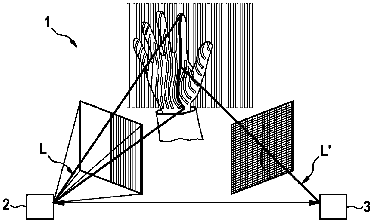
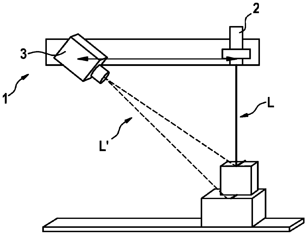
[0040] exist figure 1 A schematic diagram of an optical sensor 1 according to an embodiment of the invention is shown in . The optical sensor 1 is here a structured light sensor, for example a strip projection sensor. The optical sensor comprises a light source module 2 configured to generate a light signal L. In strip projection, the object to be measured is illuminated here in a sequence of strips, in particular of different widths, which are alternately bright and dark. At a determined moment, a complete set of strips is projected onto the object. At immediately following moments, different sets of strips are projected onto the object. Here, an exemplary light signal L, here a light beam L, is reflected on the object, whereby a reflected light beam L' is generated corresponding to the light signal L'.

[0041] The detection module 3 , which is arranged at a fixed distance from the light source module 2 and at a fixed viewing angle relative to the light source module 2 ,...


PUM


Abstract

The invention relates to an optical sensor for distance and / or speed measurement, with a light source module for producing a light signal, and a detection module for detecting a light signal, characterised in that the light source module comprises a modulator for modulating the light signal, the modulator being configured such that the light signal contains identification information following themodulation, and the detection module being configured to detect and identify indentification information of the detected light signal.

Description

technical field [0001] The invention proceeds from an optical sensor for distance measurement and / or speed measurement according to the preamble of claim 1 . Furthermore, the invention proceeds from a system for mobility monitoring of an autonomous vehicle according to the preamble of claim 8 and a method for mobility monitoring of an autonomous vehicle according to the preamble of claim 10 Set off. Background technique [0002] Optical sensors of this type are already known and are used, for example, in robotics for the monitoring of the travel path of autonomous vehicles. For example, ground vehicles such as forklift trucks that move autonomously in storage warehouses are equipped with such sensors, or in the private sector robot vacuum cleaners are equipped with such sensors for reliable navigation and object recognition and / or for the prevention of danger zone. [0003] A disadvantage here is that in systems with several autonomous vehicles of this type, the optical s...

Claims


Application Information

Patent Timeline
Patent Type & Authority Applications(China)
IPC IPC(8): G01S17/10G01S17/46G01S17/93G01S7/484G01S17/931
CPCG01S17/10G01S17/46G01S7/484G01S17/931G01S17/58
Inventor J·格拉博夫斯基T·格伦德曼
Owner ROBERT BOSCH GMBH
Why Eureka
Try Eureka