
Mps generation system and method

A current pulse and circuit technology, applied in the field of maintenance power characteristic generation system, can solve problems such as short-term changes in voltage output

Active Publication Date: 2019-05-21
MICROSEMI P O E LTD
View PDF4 Cites 0 Cited by
  • Summary
  • Abstract
  • Description
  • Claims
  • Application Information

AI Technical Summary

Problems solved by technology

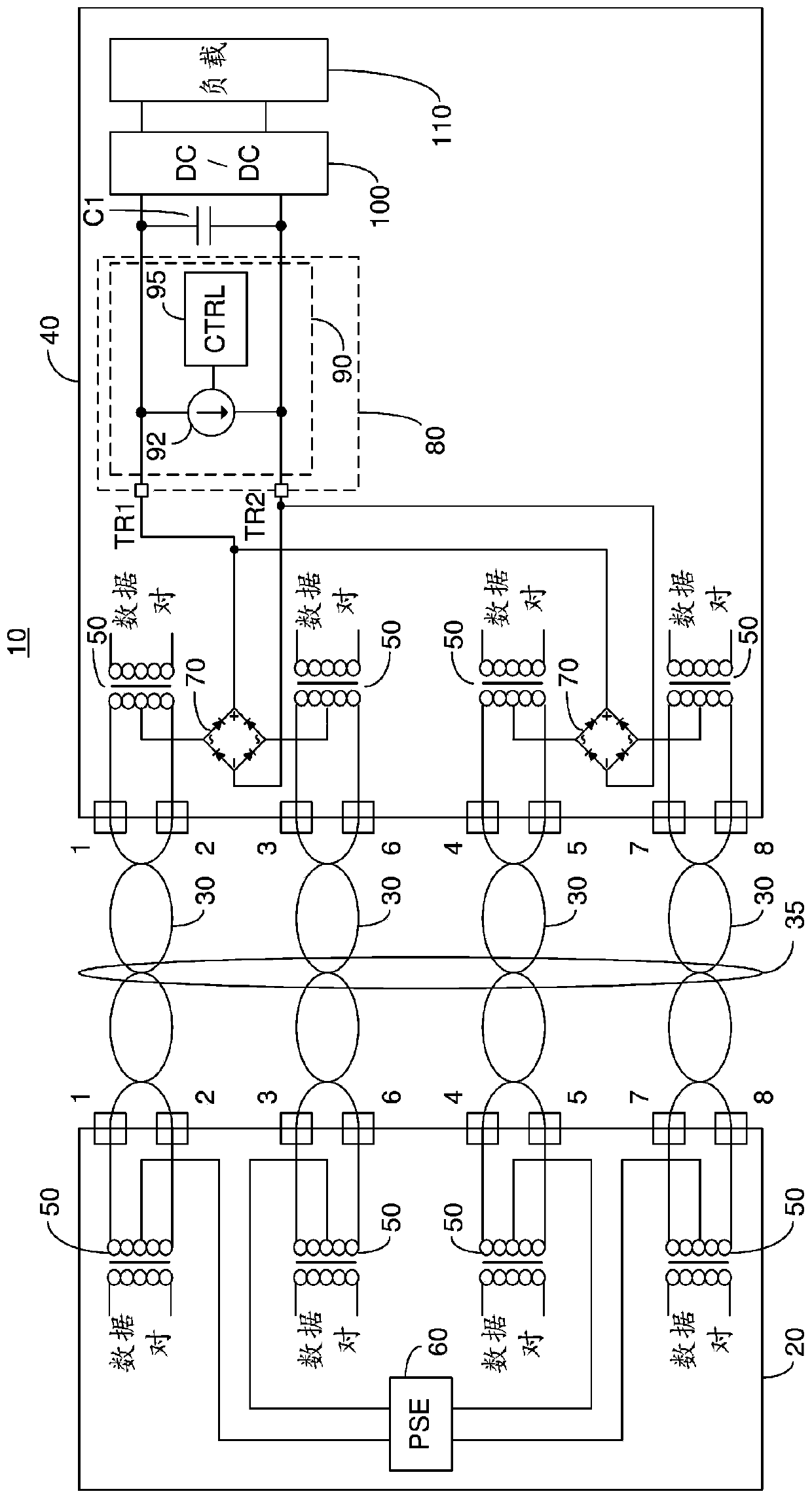
Due to load changes or cross-port load regulation, there may be short-term changes in the voltage output of the PSE 60, lasting up to 10ms in a typical multiport system

Method used


Image

  • Mps generation system and method
  • Mps generation system and method
  • Mps generation system and method

Examples


Embodiment Construction

[0025] Before explaining at least one embodiment of the invention in detail, it is to be understood that the invention is not limited in application to the details of construction and the arrangement of parts set forth in the following description or shown in the drawings. The invention is applicable to other embodiments or of being practiced or carried out in various ways. Also, it is to be understood that the phraseology and terminology herein are for the purpose of description only and should not be regarded as limiting.

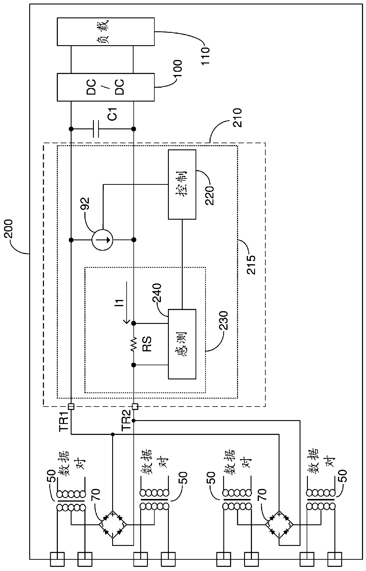
[0026] Figure 2A A high level schematic diagram of PD 200 is shown. The PD 200 includes: a plurality of data transformers 50; a pair of diode bridges 70; a PD interface 210; a DC / DC converter 100; PD interface 210 includes: MPS circuit 215 , which includes current source 92 ; control circuit 220 ; and power sense circuit 230 . The current sensing circuit 230 includes: a sensing resistor RS; and a sensing function module 240 . The sense resistor RS re...


PUM


Abstract

An MPS generation method, the method constituted of: at a predetermined frequency, alternately outputting a first MPS current pulse (300) for a predetermined first time period (T1-T2, T3-T4) and not outputting the first MPS current pulse for a predetermined first off time period (T2-T3, T4-T6); during the first time period (T1-T2, T3-T4), determining the magnitude of a current drawn by an input capacitor of a DC to DC converter; and responsive to the determined input capacitor current magnitude, outputting between the first terminal and the second terminal a second MPS current pulse for a predetermined second time period (T4-T5) during the predetermined first off time period (T4-T6).

Description

technical field [0001] The present invention relates generally to the field of powered device (PD) interfaces, and in particular to maintain power signature (MPS) generation systems and methods. Background technique [0002] In a Power over Ethernet (PoE) system, the Power Sourcing Equipment (PSE) is arranged to disconnect power when it detects that no PD is drawing current. In particular, the PSE is arranged to detect whether there is a predetermined minimum current drawn for a predetermined minimum period of time within a predetermined window. PDs that supply the predetermined minimum current for a predetermined minimum period of time are considered to provide a maintenance power characteristic (MPS). Therefore, to prevent the PSE from closing the port while the PD is in standby mode, the PD generates an MPS which will draw a current from the PSE with a magnitude greater than a predetermined minimum current threshold. To reduce power consumption during the PD's standby m...

Claims


Application Information

Patent Timeline
IPC IPC(8): H04L12/10H04L12/40G05F3/30
CPCG06F1/266H04L12/40045G05F1/70G05F3/30H04L12/10G06F1/3206G01R27/16G06F1/3209H02J3/02
Inventor Y·达什南
Owner MICROSEMI P O E LTD
Learn More