
Spinning spin roller mechanism

The technology of a rotary wheel and a rotary wheel head is applied in the field of spinning rotary wheel mechanism, which can solve the problems of too long rotary wheel arm, unsuitable application, and inability to meet the same height of reduction of three rotary wheels in internal spinning, so as to improve rigidity. Effect

Inactive Publication Date: 2019-05-24
AEROSPACE INST OF ADVANCED MATERIALS & PROCESSING TECH
View PDF8 Cites 0 Cited by
  • Summary
  • Abstract
  • Description
  • Claims
  • Application Information

AI Technical Summary

Problems solved by technology

[0002] Three-wheel powerful external spinning is currently the most important external spinning method for cylindrical parts. It has the characteristics of large spinning tonnage, automatic centering of three-wheels, and high spinning accuracy. It is widely used in thick-walled difficult-to-form materials. External spinning, but the structure of the rotary wheel mechanism is complex and huge, which cannot be applied to the process of die ring spinning, where the rotary wheel must work in a narrow space inside the blank
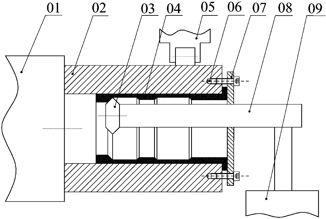
Existing internal spinning equipment such as figure 1 (While spinning machine body 01, mandrel 02, rotary wheel 03, workpiece 04, balance wheel mechanism 05, screw 06, binder ring 07, rotary wheel arm 08, lateral carriage 09), the lateral L Type cantilever type single rotary wheel internal spinning mechanism, the shaft and radial feed of the rotary wheel 03 are driven by the lateral carriage 09 to drive the L-shaped rotary wheel arm 08 fixed to it, driven by the motor, the overall axial and radial feed Mobile implementation, the spinning wheel arm is too long, the rigidity of single wheel spinning is extremely low, automatic centering spinning cannot be realized, and the spinning force is small, it is impossible to carry out spinning processing of thick-walled difficult-to-form materials, and cannot meet the processing of high-precision products
[0004] Patent 201320851050.1 A device for powerful counter-wheel spinning provides an inner spinning wheel structure, which cannot realize automatic centering of the three-roller, and cannot meet the requirement of consistent reduction of the inner spinning three-roller; at the same time, This patent uses the T-groove on the wedge surface as the support surface. There is a gap in the sliding fit, the positioning accuracy is poor, and it is easy to wear after long-term use, and the positioning accuracy cannot be guaranteed. It cannot meet the requirements for internal spinning with higher spinning accuracy.

Method used


Image

  • Spinning spin roller mechanism
  • Spinning spin roller mechanism
  • Spinning spin roller mechanism

Examples


Embodiment Construction

[0019] The present invention will be described in detail below in conjunction with specific examples and accompanying drawings.

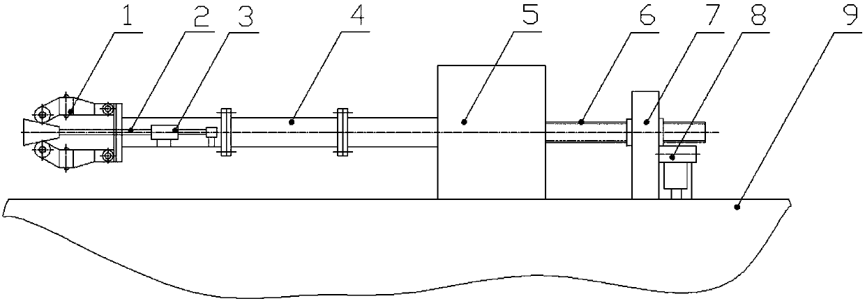
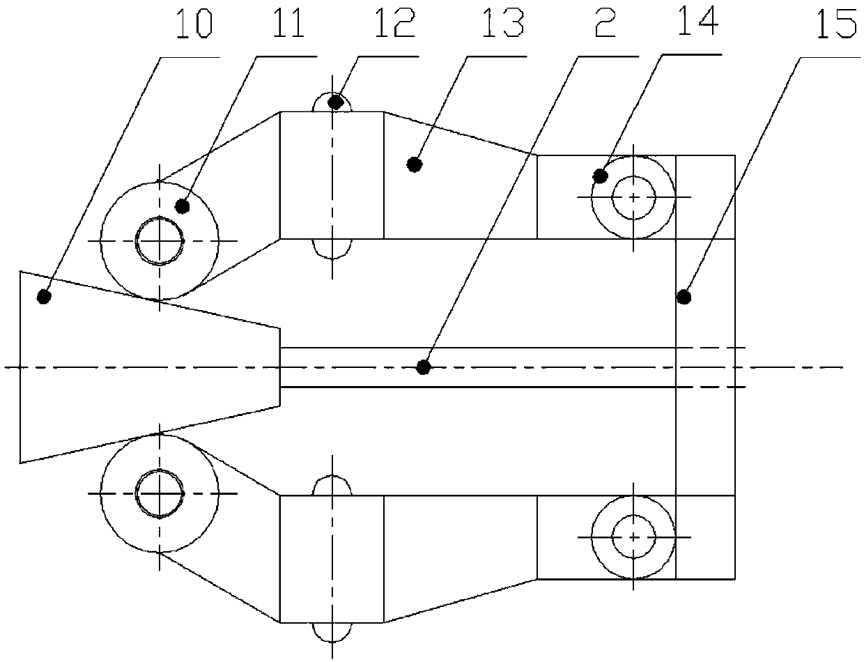
[0020] The present invention as figure 2 As shown, it includes the rotary wheel head mechanism 1, the rotary wheel radial feed screw 2, the rotary wheel radial feed drive motor 3, the rotary wheel arm 4, the rotary arm seat 5, the axial feed screw 6, the feed Box 7 and axial feed drive motor 8, feed box 7 is fixed on the tail end of spinning machine tool 9, and axial feed drive motor 8 is installed inside it, and its center line coincides with the machine tool spindle center line; Installed on the guide rail of the spinning machine tool 9, its center line coincides with the center line of the machine tool spindle, and is connected to the feed box 7 through the axial feed screw 6, and the axial feed screw 6 can be driven by numerical control programming to make the arm seat 5. Axial feed movement with precise speed and position control; the rotary ...


PUM


Abstract

The invention provides a spinning spin roller mechanism. The spinning spin roller mechanism comprises a spin roller head mechanism, a spin roller radial feeding structure, a spin roller arm, a spin arm seat and an axial feeding structure, wherein the spin roller head mechanism is composed of three sets of spin roller assemblies which are uniformly distributed in the circumferential direction, a spin roller head main body and an iron wedge, each set of spin roller assembly comprises a supporting rolling body, a spin roller, a connecting rod and a connecting rod shaft. According to the spinningspin roller mechanism, through cooperation between the iron wedge and the spin roller assemblies, axial and radial motion capable of being precisely numerically controlled is converted into the radialmotion of a spin roller head, the precise numerical control of radial feeding of the spin rollers is realized, then the precise axial and radial motion conversion of the spin rollers in a narrow space is realized, and the precise control of radial feeding amount of the spin rollers is met.

Description

technical field [0001] The invention relates to a spinning wheel mechanism, which belongs to the technical field of internal spinning. Background technique [0002] Three-wheel powerful external spinning is currently the most important external spinning method for cylindrical parts. It has the characteristics of large spinning tonnage, automatic centering of three-wheels, and high spinning accuracy. It is widely used in thick-walled difficult-to-form materials. External spinning, but the structure of the rotary wheel mechanism is complex and huge, which cannot be applied to the process of die ring spinning, where the rotary wheel must work in a narrow space inside the blank. [0003] Internal spinning technology is a relatively new spinning technology. Using internal spinning technology can produce cylindrical rotary parts with inner circumferential reinforcement ribs. It has the characteristics of high product precision, high yield and high production efficiency. A certain...

Claims


Application Information

Patent Timeline
Patent Type & Authority Applications(China)
IPC IPC(8): B21D22/14
Inventor 马世成王东坡张月倩张晨汪宇羿赵文龙
Owner AEROSPACE INST OF ADVANCED MATERIALS & PROCESSING TECH
Learn More