
Cross main machine and grinding filing machine

A technology of cross and main engine, which is applied in the direction of grinding machines, grinding machine parts, grinding/polishing equipment, etc. It can solve the problems that the column bears a large bending moment and cannot move the grinding head in multiple directions, so as to meet the requirements of fast lifting of workpieces and improve flexibility. performance and bending moment improvement effect

Pending Publication Date: 2019-05-24
张敏
View PDF0 Cites 0 Cited by
  • Summary
  • Abstract
  • Description
  • Claims
  • Application Information

AI Technical Summary

Problems solved by technology

The column of the existing equipment bears a large bending moment and cannot provide smooth and precise multi-directional movement for the grinding head

Method used


Image

  • Cross main machine and grinding filing machine
  • Cross main machine and grinding filing machine
  • Cross main machine and grinding filing machine

Examples


Embodiment 1

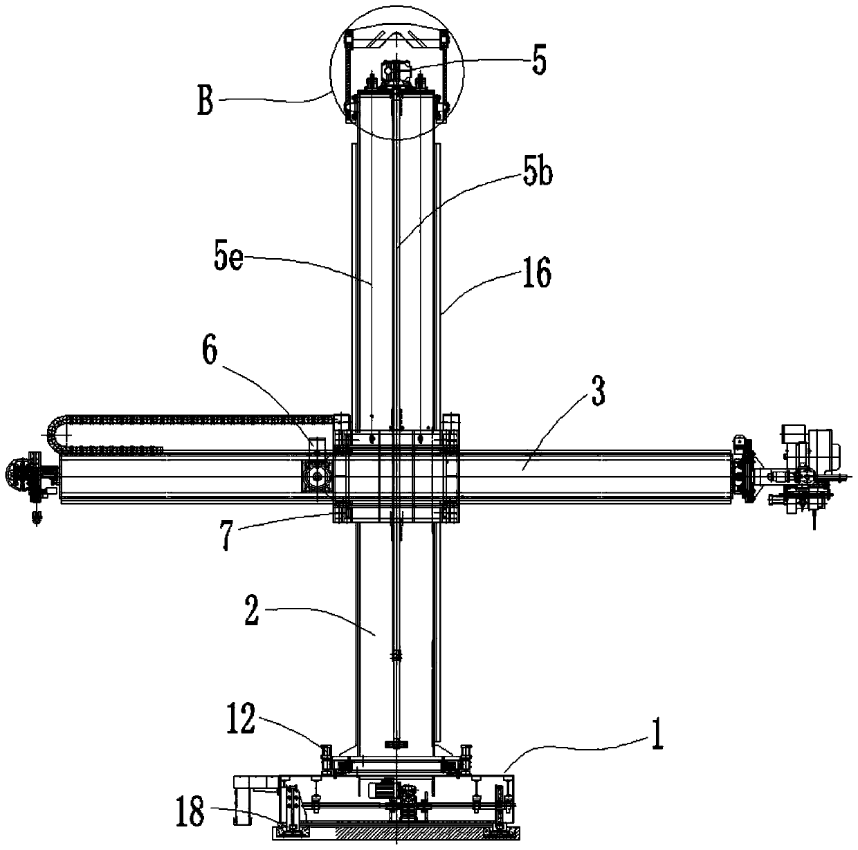
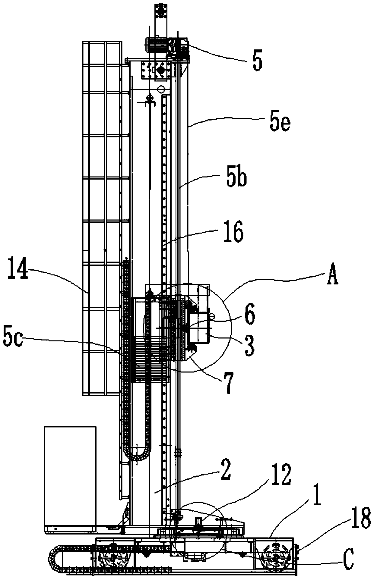
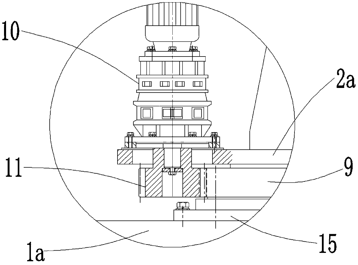
[0058] The cross host has the advantages of stable structure, stable movement and high precision, such as figure 1 , figure 2 , image 3 , Figure 4 , Figure 5 , Image 6 , Figure 7 As shown, it is specially set to the following structure:

[0059] It includes an operating machine trolley 1, a column 2, a cross beam 3, an electric slewing mechanism, a lifting mechanism 5, a traverse mechanism 6, and a sliding plate 7.

[0060] The manipulator trolley 1 is a super-heavy walking trolley, which is used to carry components connected to it and to realize linear travel in the X direction. The operating machine trolley 1 mainly includes a trolley base 1a, a traveling geared motor 1b installed on the trolley base 1a, a traveling wheel 1c that is connected to the traveling geared motor 1b through a coupling, and the operating machine trolley 1 passes through the traveling wheel 1c is installed on a pre-laid walking track, which provides horizontal guidance for the X axis.

[0061] An ele...

Embodiment 2

[0075] This embodiment is further improved on the basis of the above embodiments, and particularly adopts the following configuration structure:

[0076] A number of anti-overturning structures 18 are fixedly installed at the side plates of the trolley base 1a of the operating machine trolley 1 by bolts, and the anti-overturning structures 18 are located above the walking track.

[0077] Specifically, the anti-overturning structure 18 mainly includes two anti-roll plates 18a that are integrally vertical plates. The bottom end of the anti-roll plate 18a has an escape groove for avoiding the walking track, so that the entirety is a vertical plate with a hook at the bottom. The anti-roll plate 18a is fixedly connected to the side plate of the trolley base 1a by bolts. There is a gap between the two anti-roll plates 18a in a single anti-roll structure 18, and the avoidance grooves of the two anti-roll plates 18a are arranged oppositely to form a T-shaped groove for clamping the limit w...

Embodiment 3

[0079] This embodiment also provides a file grinder on the basis of the above-mentioned embodiment, and particularly adopts the following arrangement structure:

[0080] Including the cross mainframe in embodiment 1, the grinding head of the grinding head and the welding head of the surfacing welding head are respectively fixedly installed at the two ends of the beam 3. After installing the grinding head of the grinding head machine on the cross host, the grinding head can move smoothly and stably in multiple directions.


PUM


Abstract

The invention provides a cross main machine and a grinding filing machine, relates to the field of grinding equipment, and solves the problem that stable and precise multi-way movement cannot be provided for a grinding head in the prior art. A stand column in a cross is connected with an electric rotary mechanism to realize C-direction rotation, wherein the electric rotary mechanism is connected with a manipulator trolley to realize X-direction movement; a slide plate is movably connected with the stand column to realize Z-direction movement; a beam is movably connected with the slide plate torealize Y-direction movement; a lifting reduction motor is mounted on the stand column and is connected to a lead screw; the lead screw is in transmission connection to the slide plate through a leadscrew pair, so that axial motion precision, along the lead screw, of the slide plate is improved; a steel wire rope is wound on a fixed pulley at the top end of the stand column, and is separately connected with the slide plate and a counterweight to improve motion stability and precision of the grinding heads; and a side-sliding mechanism is mounted on the stand column and is in transmission connection to the beam. According to the grinding filing machine provided by the invention, multi-way high-precision stable movement of the grinding heads can be realized after the grinding heads are mounted at the two ends of the beam.

Description

Technical field [0001] The invention relates to the field of grinding equipment, specifically, a cross mainframe and a file grinder. Background technique [0002] Domestic nuclear reactors and tanks similar to high-pressure heavy vessels are basically welded by steel plates, and their welds are uneven. Grinding tools are required to automatically adapt to this change in welds. [0003] At present, there is a lack of mid- to high-end equipment for grinding and polishing domestic nuclear reactors and similar high-pressure heavy vessels. The column of the existing equipment bears a large bending moment and cannot provide smooth and accurate multi-directional movement for the grinding head. Therefore, it is a special equipment developed by combining the characteristics of a new type of high-efficiency strong abrasive belt and high-speed grinding wheel grinding. Summary of the invention [0004] The purpose of the present invention is to design a cross main machine and a filing machine...

Claims


Application Information

Patent Timeline
Patent Type & Authority Applications(China)
IPC IPC(8): B24B19/00B24B41/00
Inventor 张敏
Owner 张敏
Learn More