Cavity filter frequency adjustment mechanism
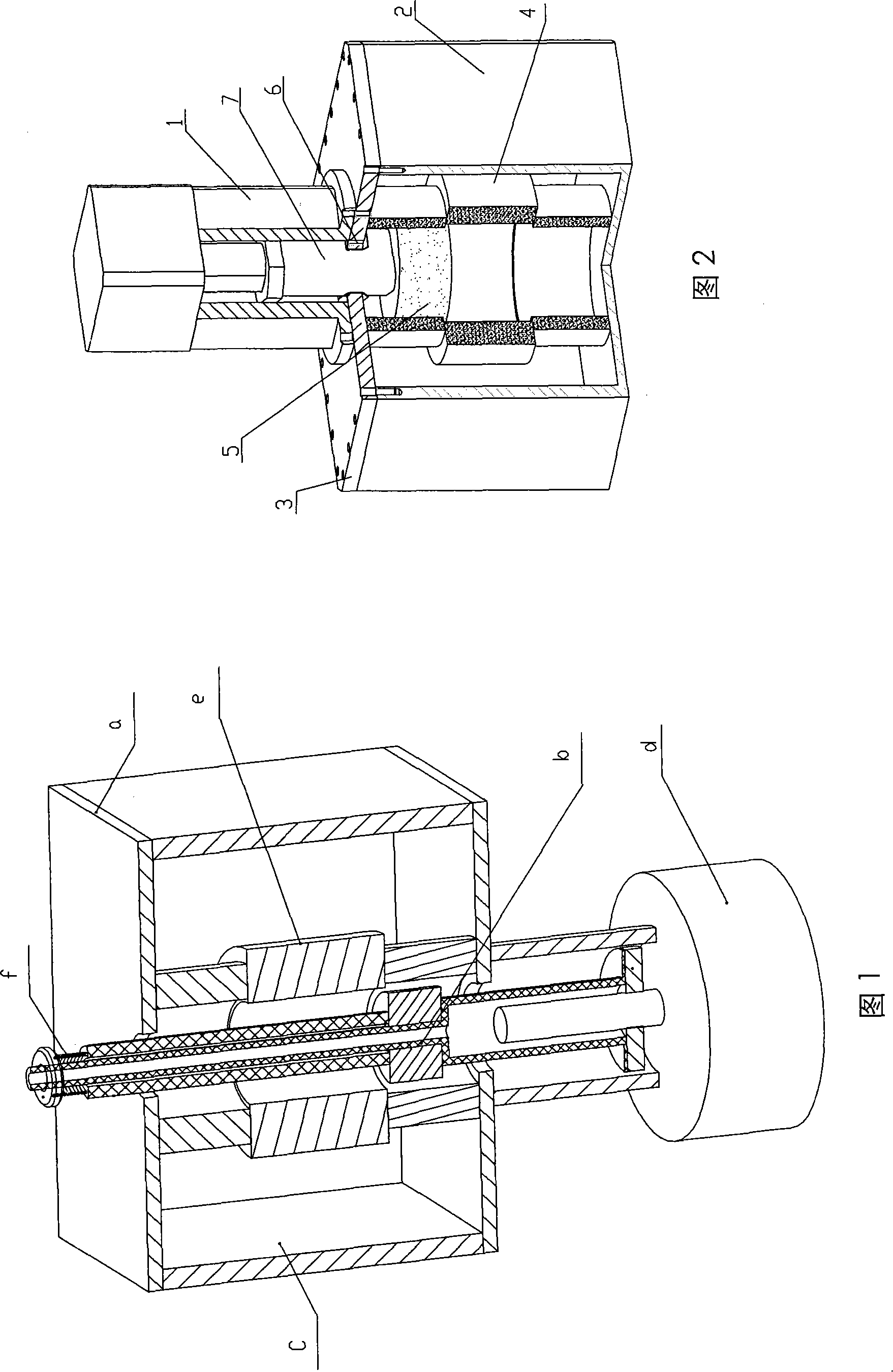
A cavity filter and frequency adjustment technology, which is applied to waveguide devices, resonators, electrical components, etc., can solve the problem that the end is easy to deviate from the axis line, the connecting rod b and the cover plate are seized, and the rigidity of the connecting rod b is poor and other problems, to achieve the effect of reducing processing steps, facilitating assembly, and ensuring rigidity
- Summary
- Abstract
- Description
- Claims
- Application Information
AI Technical Summary
Problems solved by technology
Method used
Image
Examples
Embodiment 1
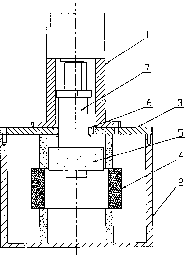
[0042] Such as Figure 2 ~ Figure 4 As shown, the present invention includes: a cavity body 2, an inner dielectric body 5, an outer dielectric body 4 and a connecting rod 7, the cavity body 2 is a thin-walled cylinder structure, and the outer dielectric body 4 is also A cylindrical structure with an inner cavity machined in the center is fixedly placed in the center of the inner cavity of the cavity body 2, and the center line of the two must be guaranteed to be within a certain tolerance range during assembly. The connecting rod 7 is placed in the inner cavity of the cavity body 2 and is connected with the transmission device 1, wherein the transmission device 1 includes a motor (not shown in the figure) and a leading screw 8, and the leading screw 8 is connected with the connecting rod 7. Driven by the motor, the connecting rod 7 can be moved axially in the inner cavity of the cavity body 2 through the lead screw 8 . The inner dielectric body 5 is installed on the connectin...
Embodiment 2
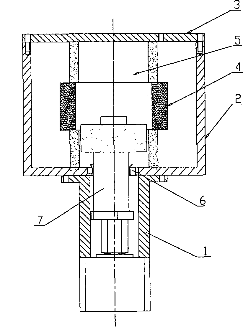
[0047] Such as Figure 3a As shown, the composition and coordination of the parts of this embodiment are the same as those of the first embodiment, the cover plate 3 is installed on the cavity body 2, the difference is that the transmission device 1, the clamping device 6, the connecting rod 7, etc. are all inverted At the bottom of the cavity body 2, the tightening device 6 is set in the corresponding groove on the bottom end of the cavity body 2, which cooperates with the working surface 7.1 of the connecting rod, and can also realize the automatic centering function of the connecting rod 7 .
Embodiment approach
[0049] Such as figure 2 , image 3 As shown, the transmission device 1 connected to the connecting rod 7 of the present invention is fixed on the cavity body 2 or placed on the cover plate 3 provided on the cavity body 2, and the connecting rod 7 is placed on the transmission device 1. Therefore, the clamping device 6 can also be set in the groove corresponding to the transmission device 1, and it can cooperate with the working surface 7.1 of the connecting rod to realize the automatic movement of the connecting rod 7. Centering function. This can be the fourth embodiment of the arrangement of the tightening device of the present invention.
[0050] In the above-mentioned structural embodiments, the part of the tightening device 6 of the present invention that is in contact with the working surface 7.1 of the connecting rod and the part that is in contact with the inner wall of the groove cavity can also be combined by two components, wherein the part that is in contact wit...
PUM
 Abstract
Description
Claims
Application Information
 - R&D
- Intellectual Property
- Life Sciences
- Materials
- Tech Scout
- Unparalleled Data Quality
- Higher Quality Content
- 60% Fewer Hallucinations
Browse by: Latest US Patents, China's latest patents, Technical Efficacy Thesaurus, Application Domain, Technology Topic, Popular Technical Reports.
© 2025 PatSnap. All rights reserved.Legal|Privacy policy|Modern Slavery Act Transparency Statement|Sitemap|About US| Contact US: help@patsnap.com


