
A method of using a non-magnetic clamping workpiece rotary table for a bearing ball base surface grinding machine

A technology of rotary table and bearing balls, which is applied in the direction of grinding machine parts, grinding workpiece supports, grinding bed, etc., can solve the problems of low grinding precision, easy axial movement, poor stability, etc., and achieve Improve the grinding precision, ensure the grinding force, and reduce the effect of round runout of the end face

Active Publication Date: 2020-07-21
LUOYANG LIBO NUMERICAL CONTROL TECH CO LTD
View PDF11 Cites 0 Cited by
  • Summary
  • Abstract
  • Description
  • Claims
  • Application Information

AI Technical Summary

Problems solved by technology

[0003] In order to solve the above problems, the present invention provides a method for using a non-magnetic clamping workpiece rotary table for a bearing ball base surface grinding machine. The grinding on the grinding machine overcomes the problems of poor stability, easy axial movement, and low grinding precision that are easy to occur during tapered roller grinding, thereby reducing the round runout of the end surface of the tapered roller ball base surface and improving grinding efficiency

Method used


Image

  • A method of using a non-magnetic clamping workpiece rotary table for a bearing ball base surface grinding machine
  • A method of using a non-magnetic clamping workpiece rotary table for a bearing ball base surface grinding machine
  • A method of using a non-magnetic clamping workpiece rotary table for a bearing ball base surface grinding machine

Examples


Embodiment Construction

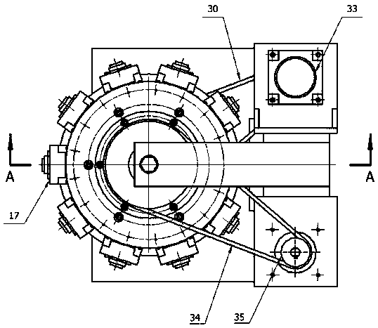
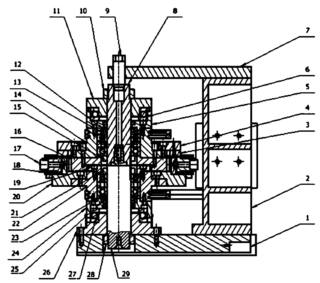
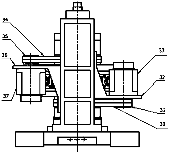
[0025] The invention relates to a method for using a non-magnetic clamping workpiece rotary table for a bearing ball base surface grinding machine. The invention realizes the grinding of tapered rollers on the ball base surface grinding machine through the self-made non-magnetic clamping workpiece rotary table.

[0026] to combine Figure 1-3 , the non-magnetic clamping workpiece rotary table of the present invention includes a base plate 1, a column 2, a gear plate 3, an upper ring connecting plate 4, an upper gland 5, a first thrust bearing 6, an upper pressure plate 7, an upper spindle 8, and an upper compression shaft 9. The first lock nut 10, the positioning pressure sleeve 11, the second thrust bearing 12, the upper washer 13, the upper rotary plate 14, the second lock nut 15, the flat plate 16, the flange plate 19, the lower ring connecting plate 20, The third lock nut 21, the lower rotary disc 22, the lower washer 23, the lower gland 24, the third thrust bearing 25, th...


PUM


Abstract

The invention discloses a use method of a revolving platform of a non-magnetic clamping workpiece used for a bearing ball base surface grinding machine. A self-positioning device with buffering is used, an inner taper hole of the lower end of an upper main shaft is connected with an outer taper surface of the upper end of a lower main shaft in a matched mode, an upper pressing shaft is connected into inner threads of an upper pressing plate in a screwed mode, the lower taper surface of the upper pressing shaft is connected into a taper hole of the upper end of the upper main shaft, and the condition that the upper main shaft and the lower main shaft are provided with a same central axis is ensured; the condition that the upper main shaft and the lower main shaft are stationary in the grinding process of an upper revolving disc and a lower revolving disc is ensured; self-rotation grinding of a tapered roller is realized from a second motor, a belt, an upper belt wheel, the upper revolving disc, a gear disc to a gear shaft; and orbital revolution grinding of the tapered roller is realized from a first motor, a lower belt, a lower belt wheel to the self-positioning device with buffering around the central axis of the lower main shaft. Phenomena that the tapered roller is prone to having poor stability, generating axial movement and the like are overcome, end surface circular run-out errors of the ball base surface of the tapered roller are reduced, and the grinding efficiency and precision are improved.

Description

technical field [0001] The invention belongs to the technical field of special equipment for bearing grinding, in particular to a method for using a non-magnetic clamping workpiece rotary table used for a bearing ball base surface grinding machine. Background technique [0002] The domestic grinding machine for grinding the spherical surface of tapered rollers adopts spherical surface grinding machines. During the grinding process of tapered rollers, the tapered rollers to be ground are located in the tooth grooves of the isolation disk. Since the rotation speed of the left guide wheel is higher than that of the right guide The wheel disc is lower and the two guide wheel discs rotate in opposite directions with different speeds. The manufacturing accuracy of the working cone surface of the isolation disc and the left and right guide discs is difficult to meet the design requirements, resulting in the extension line of the working surface of the isolation disc not being able t...

Claims


Application Information

Patent Timeline
Patent Type & Authority Patents(China)
IPC IPC(8): B24B41/06B24B41/02B24B47/12B24B47/00
Inventor 张洛平闫姣姣李华
Owner LUOYANG LIBO NUMERICAL CONTROL TECH CO LTD
Learn More