Bidirectional quantitative powder supplying and spreading device for additive manufacturing
A powder spreading device and additive manufacturing technology, applied in the field of additive manufacturing, can solve the problems of large span of powder spreading scraper structure, reduced work efficiency, large molding area, etc., to improve the quality of powder spreading, improve sintering quality, reduce small dust effect
- Summary
- Abstract
- Description
- Claims
- Application Information
AI Technical Summary
Problems solved by technology
Method used
Image

Examples
Embodiment Construction
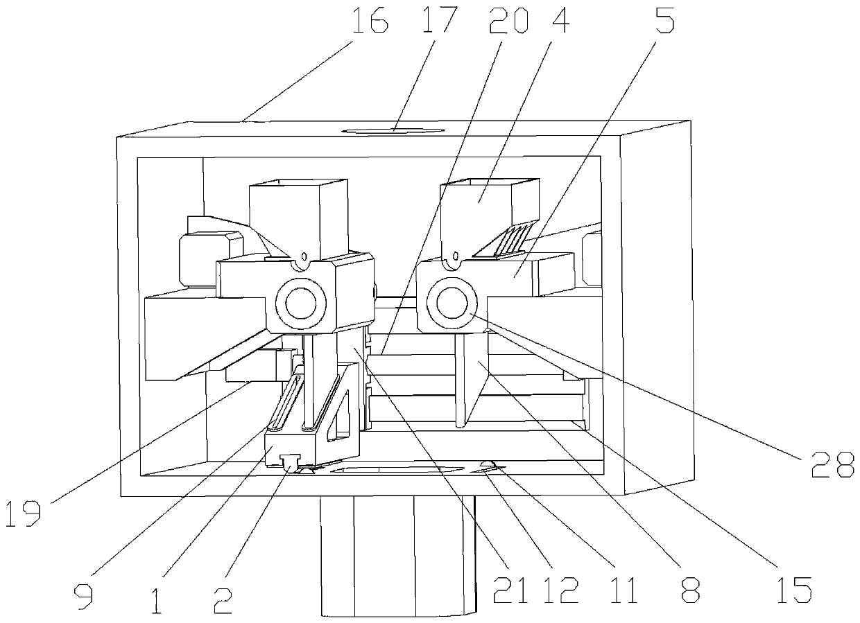
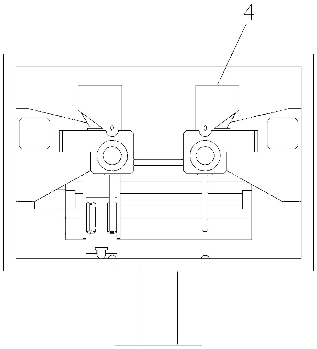
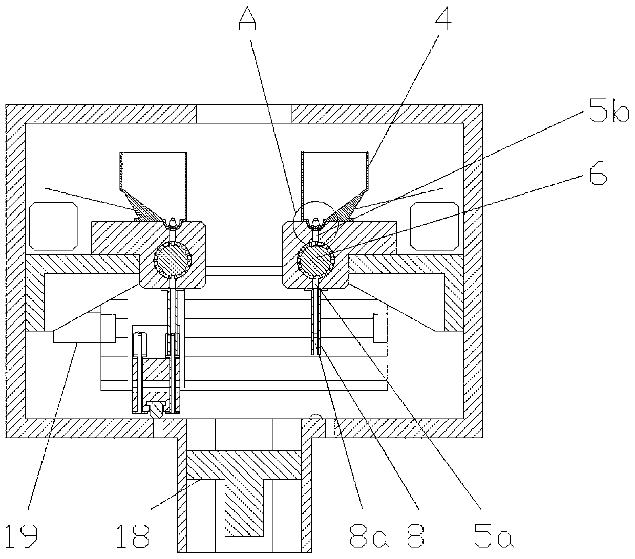
[0032] figure 1 It is a schematic diagram of the three-dimensional structure of the present invention; figure 2 It is a structural schematic diagram of the present invention; image 3 It is a schematic cross-sectional structure diagram of the present invention; Figure 4 for image 3 Schematic diagram of the enlarged structure at point A; Figure 5 It is a schematic diagram of the structure of the powder supply roller driving device; Image 6 A schematic diagram of the enlarged structure of the boss; Figure 7 It is a schematic diagram of the structure of the scraper mounting seat; Figure 8 It is a schematic diagram of the lining structure of the flow channel; Figure 9 It is a schematic diagram of the structure of the powder supply roller mounting seat; Figure 10 It is a schematic diagram of the powder supply roller structure; Figure 11 It is a schematic diagram of the structure of the powder supply box;
[0033] In this embodiment, the left, right, front and rea...
PUM
 Abstract
Description
Claims
Application Information