
A fan aerodynamic structure

A fan and radial guide vane technology, applied in the system field, can solve the problems of low noise, unsatisfactory airborne equipment "compact structure, and inability to make full use of axial flow fans" to achieve the effect of compact structure and improved static pressure efficiency

Active Publication Date: 2020-11-20
GUIZHOU YONGHONG AVIATION MACHINERY
View PDF9 Cites 0 Cited by
  • Summary
  • Abstract
  • Description
  • Claims
  • Application Information

AI Technical Summary

Problems solved by technology

[0004] The present invention aims to provide a new type of fan aerodynamic structure to solve the problem of "small flow, large pressure rise" which cannot fully utilize the advantages of axial flow fans and cannot meet the needs of airborne equipment with "compact structure, low noise and axial air intake / exhaust". "The problem of using demand

Method used


Image

  • A fan aerodynamic structure
  • A fan aerodynamic structure
  • A fan aerodynamic structure

Examples


Embodiment Construction

[0025] The present invention will be further described below in conjunction with accompanying drawing and specific embodiment:

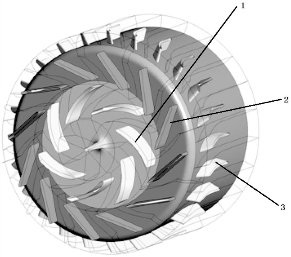
[0026] It should be noted that, in this embodiment, taking the axial direction of the centrifugal impeller as the reference, the centrifugal blades 1 are distributed in a plane (end surface of the centrifugal impeller) perpendicular to the axial direction, arranged radially along the inner circumference of the plane, and the radial guide vanes 2 are arranged in a plane circumference perpendicular to the axial direction, and the circumference is coaxial with the centrifugal impeller, and the axial guide vanes 3 are arranged parallel to the axial direction and along the plane circumference perpendicular to the axial direction.

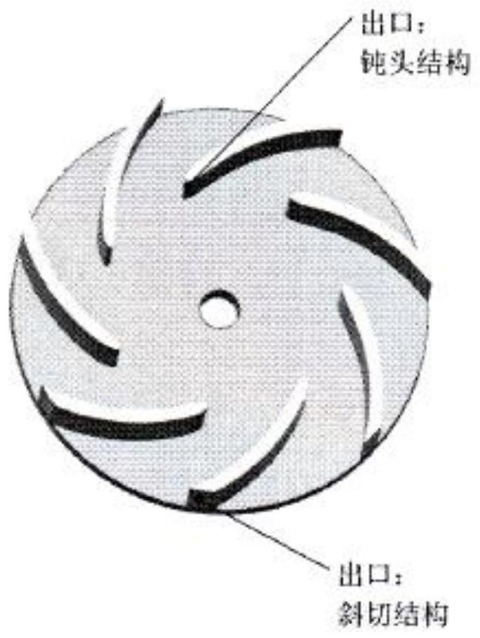
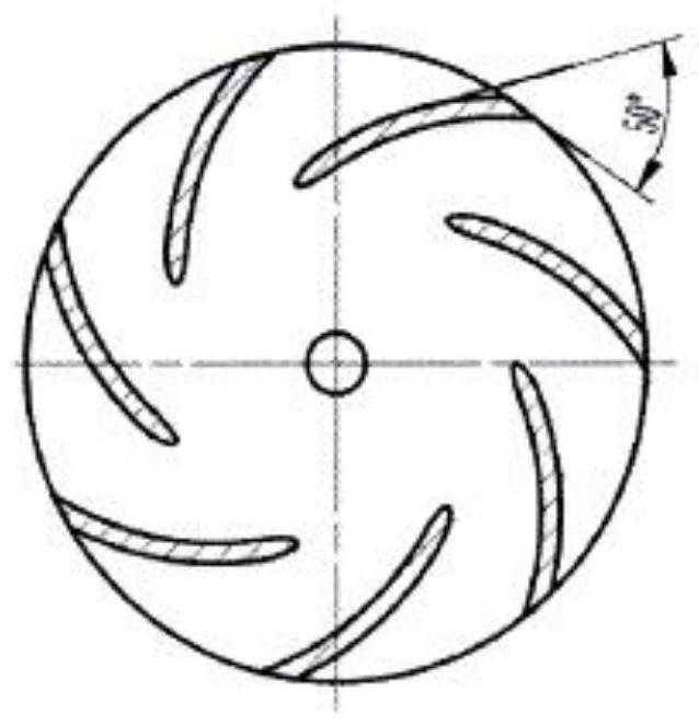
[0027] Such as Figure 1 ~ Figure 4 As shown, the novel fan aerodynamic structure provided by the present invention includes a centrifugal impeller, radial guide vanes 2 and axial guide vanes 3 . Centrifugal blade 1 is a movin...


PUM


Abstract

The invention discloses a fan pneumatic structure. The fan pneumatic structure comprises a centrifugal impeller, radial guide vanes (2) and axial guide vanes (3); the radial guide vanes (2) are located at outlets of centrifugal vanes (1) of the centrifugal impeller; the axial guide vanes (3) are located at outlets of the radial guide vanes (2); airflow sequentially passes through the centrifugal vanes (1) of the centrifugal impeller, the radial guide vanes (2) and the axial guide vanes (3), and axial air intake and axial air exhaust are realized. According to the fan pneumatic structure, the respective advantages of a centrifugal fan and axial flow air are effectively utilized, the design problem that a "small flow, large pressure rising" fan cannot carry out axial air intake / exhaust is solved, and a novel idea is provided for airborne fan design.

Description

technical field [0001] The invention belongs to the technical field of aircraft (including helicopter) environmental control, airborne pod and other systems, and in particular relates to a novel fan aerodynamic structure. Background technique [0002] The fan is a kind of machine used to transport gas, which is widely used in the aerospace field. From the perspective of energy conversion, the fan is a machine that converts the mechanical energy of the prime mover into the kinetic energy and pressure energy of the gas, ensuring that the working medium overcomes the flow. resistance to ensure that the corresponding system / equipment works normally. [0003] With the rapid development of aviation technology, due to the limitation of environmental space, higher requirements are put forward for the development of aviation fan equipment, requiring fans to be compact in structure, high in efficiency and low in noise. At present, the widely used aerodynamic structures mainly include...

Claims


Application Information

Patent Timeline
Patent Type & Authority Patents(China)
IPC IPC(8): F04D25/08F04D29/28F04D29/30F04D29/44F04D29/66
Inventor 吴永兵管新宇杨英飒
Owner GUIZHOU YONGHONG AVIATION MACHINERY
Learn More