
Blower and air conditioner having the same

a technology of blower and air conditioner, which is applied in the direction of lighting and heating apparatus, domestic cooling apparatus, heating types, etc., can solve the problems of reducing unable to effectively recover the dynamic pressure of the airflow generated by the rotation of the fan, etc., and achieves the effect of improving the static pressure efficiency of the blower

Active Publication Date: 2020-04-07
SAMSUNG ELECTRONICS CO LTD
View PDF17 Cites 0 Cited by
  • Summary
  • Abstract
  • Description
  • Claims
  • Application Information

AI Technical Summary

Benefits of technology

This design enhances the static pressure efficiency of the blower by effectively recovering dynamic pressure and improving airflow direction change, leading to improved performance and reduced noise.

Problems solved by technology

In addition, depending on the difference of the shape of the stationary blades installed in the direction in which the airflow generated by the rotation of the fan is discharged, the dynamic pressure of the airflow generated by the rotation of the fan may not be effectively recovered and the static pressure efficiency of the blower may be lowered.

Method used


Image

  • Blower and air conditioner having the same
  • Blower and air conditioner having the same
  • Blower and air conditioner having the same

Examples


Embodiment Construction

[0032]Hereinafter, embodiments of the present disclosure will be described in detail with reference to the accompanying drawings.

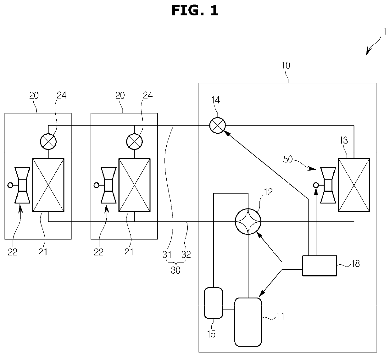
[0033]FIG. 1 is a schematic configuration diagram of an air conditioner 1 to which an embodiment of the present disclosure is applied.

[0034]The air conditioner 1 includes, for example, an outdoor unit 10 installed on a roof or the like of a building, a plurality of indoor units 20 installed on each part of the building, and a piping 30 connected between the outdoor unit 10 and the indoor units 20 and through which refrigerant circulating to the outdoor unit 10 and the indoor units 20 flows.

[0035]The outdoor unit 10 includes a compressor 11 for compressing the refrigerant, a four-way switching valve 12 for switching refrigerant passages, an outdoor heat exchanger 13 which is a device for moving heat from a high temperature object to a low temperature object, an outdoor expansion valve 14 for expanding and evaporating the condensed refrigerant liquid to low ...


PUM


Abstract

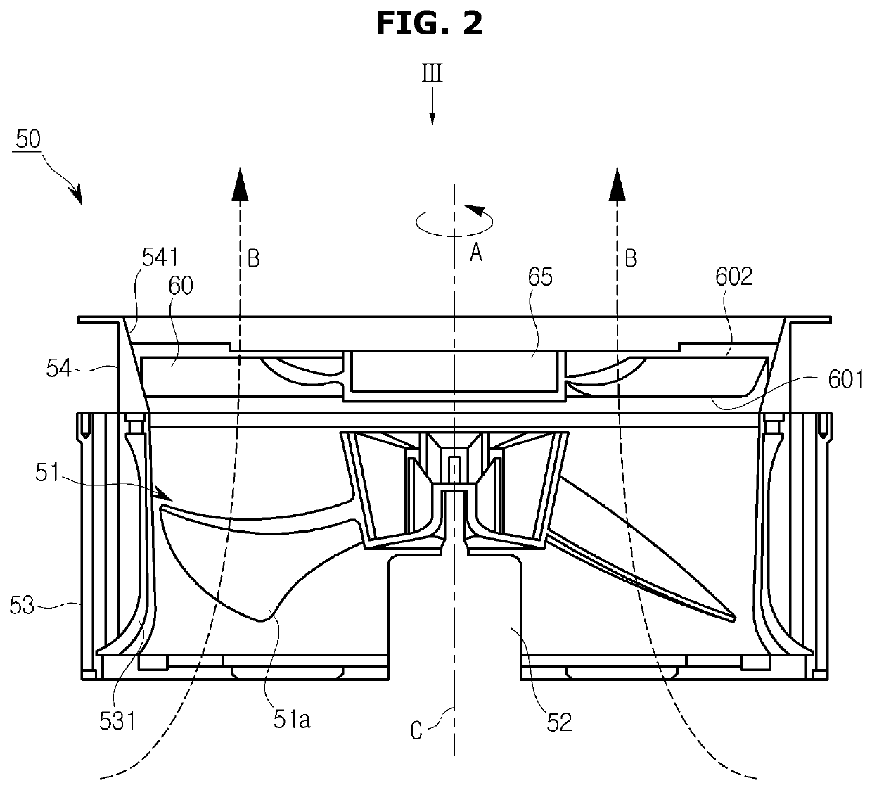
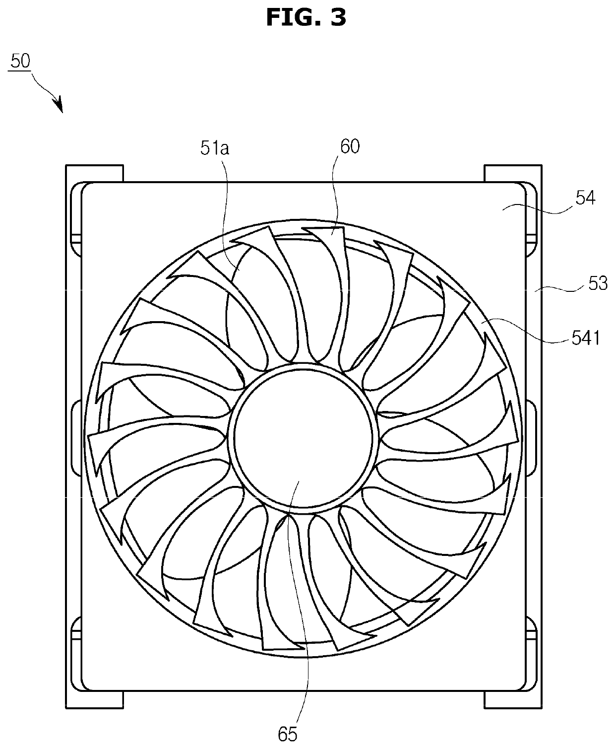
An air conditioner comprises a compressor to compress a refrigerant, a heat exchanger to move heat of the refrigerant, and a blower to blow air. The blower comprises a fan rotatable about a rotation axis, and a plurality of stationary blades installed to be a radial shape about the rotation axis in a direction in which the airflow generated by the rotation of the fan is discharged, and are curved in a direction opposite to the rotation direction of the fan from an inner circumferential portion to an outer circumferential portion. The stationary blades comprise an inlet edge, and an outlet edge, and an inlet angle formed by the inlet edge and the rotation axis and a chord angle formed by a chord connecting the inlet edge and the outlet edge and the rotation axis are larger at the inner and outer circumferential portions than at a radial center portion.

Description

CROSS-REFERENCE TO RELATED APPLICATIONS[0001]This application is a U.S. National Stage Application which claims the benefit under 35 U.S.C. § 371 of International Patent Application No. PCT / KR2015 / 007209, filed on Jul. 10, 2015, which claims the foreign priority benefit under 35 U.S.C. § 119 of Korean Patent Application No. 10-2015-0098101 filed Jul. 10, 2015, the contents of which are incorporated herein by reference.TECHNICAL FIELD[0002]The present disclosure relates to a blower and an air conditioner having the same.BACKGROUND ART[0003]A blower used in an outdoor unit of an air conditioner includes a rotating fan having a plurality of moving blades, an electric motor for driving the fan, and a plurality of stationary blades installed in a direction in which the airflow generated by the rotation of the fan is discharged.[0004]The airflow generated by the rotation of the fan having a plurality of moving blades is generally different in the blowing direction depending on the radial ...

Claims


Application Information

Patent Timeline
Patent Type & Authority Patents(United States)
IPC IPC(8): F25D17/06F25B13/00F04D29/56F24F1/08F24F1/40F04D25/08F04D29/38F24F1/38F24F1/14F04D29/54F04D25/06
CPCF24F1/14F04D29/542F25D17/067F24F1/08F25B13/00F24F1/40F04D29/38F04D29/563F04D25/08F04D29/547F24F1/38F04D25/06F04D29/544
Inventor SATO, SEIJI
Owner SAMSUNG ELECTRONICS CO LTD
Learn More