Liquid fuel heat pipe reactor

A liquid fuel and reactor technology, applied in nuclear engineering and nuclear fields, can solve the problems of fuel layer deformation, local heating unevenness, etc., achieve the effect of simplifying the heat pipe structure, avoiding excessive power, and improving heat and power distribution

Pending Publication Date: 2019-05-24
HARBIN ENG UNIV
View PDF5 Cites 10 Cited by
  • Summary
  • Abstract
  • Description
  • Claims
  • Application Information

AI Technical Summary

Problems solved by technology

However, the solid core has problems such as deformation ...

Method used


Image

  • Liquid fuel heat pipe reactor
  • Liquid fuel heat pipe reactor
  • Liquid fuel heat pipe reactor

Examples


Embodiment Construction

[0016] The technical solutions in the embodiments of the present invention will be clearly and completely described below in conjunction with the drawings in the embodiments of the present invention.

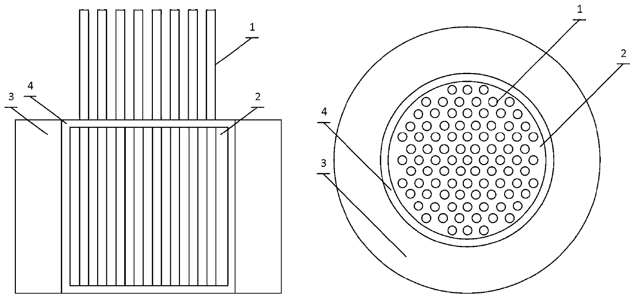
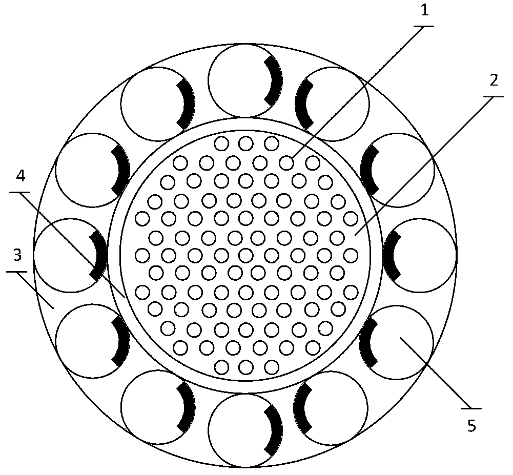
[0017] see Figure 1-4 Describe this embodiment, a liquid fuel heat pipe reactor, which includes a heat pipe 1, a fuel medium 2 and a reactor core 3, the fuel medium 2 is liquid fuel, the fuel medium 2 is located in the reactor core 3, and the heat pipe 1 is directly inserted into the fuel medium 2 in a hexagonal arrangement, and the upper part of the heat pipe 1 is located outside the fuel medium 2. The part of the heat pipe 1 inserted into the fuel medium 2 is a heating section, and the heat pipe 1 is located in the fuel medium 2 is the condensation section.

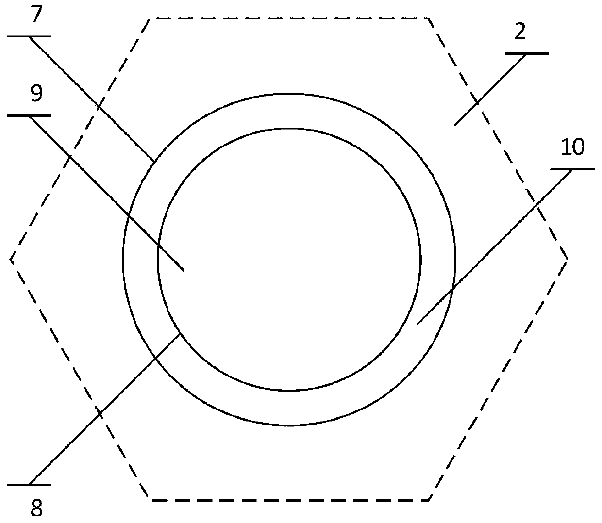
[0018] The fuel medium 2 described in this embodiment is a liquid molten salt material or a liquid metal material, which improves the heat and power distribution in the reactor. The heat pipe 1 has a double-wall structu...


PUM


Abstract

The invention provides a liquid fuel heat pipe reactor, belongs to the field of nuclear engineering and nuclear technologies, and particularly relates to a liquid fuel heat pipe reactor. The problemsthat a fuel layer of a solid reactor core is deformed, and local heating is not uniform at high temperature are solved. The liquid fuel heat pipe reactor comprises a heat pipe, a fuel medium and a reactor core. The novel heat pipe reactor is mainly provided and used for generating heat energy, and then the heat energy is converted into electric energy or kinetic energy.

Description

technical field [0001] The invention belongs to the field of nuclear engineering and nuclear technology, in particular to a liquid fuel heat pipe reactor. Background technique [0002] The heat pipe stack is the latest reactor stack type, which is composed of heat pipes and graphite or heat pipes and fuel rods inserted in graphite. Graphite acts as a neutron moderator, and fission occurs in the fuel layer, generating heat that is transferred to the heat pipe. The liquid metal in the heat pipe evaporates and moves to the condensation section, transfers heat, condenses into a liquid state, and then flows back to the reactor to start a new cycle. However, the solid core has problems such as deformation of the fuel layer at high temperature and uneven local heating. Contents of the invention [0003] In order to solve the problems in the prior art, the present invention proposes a liquid fuel heat pipe reactor. [0004] To achieve the above object, the present invention ado...

Claims


Application Information

Patent Timeline
IPC IPC(8): G21C15/257
CPCY02E30/30
Inventor 王翔
Owner HARBIN ENG UNIV
Why Eureka
Try Eureka