Equipment for resisting floating and sinking of capsule under-reamed anchor and use method of equipment

An anti-subsidence and anchor technology, which is applied to sheet pile walls, protection devices, buildings, etc., can solve the problems of complex anchor manufacture, insufficient design anchor length, and impact on the construction period, so as to save material and labor costs and improve The level of construction technology and the effect of improving stability

Pending Publication Date: 2019-05-28
山西冶金岩土工程勘察有限公司
View PDF0 Cites 0 Cited by
  • Summary
  • Abstract
  • Description
  • Claims
  • Application Information

AI Technical Summary

Problems solved by technology

[0002] At present, during the construction of the building, the expansion bolt will float up during the grouting process, and will sink after the grouting. The sinking anchor rod is uneven on the bottom surface of the foundation pit, which will have a certain impact on the later construction. If the length of the anchor rod exposed on the bottom surface of the foundation pit is short, another section of the anchor rod needs to be welded or nut-socketed. If the length of the anchor rod on the ground plane is long, a part needs to be cut off to meet the anchorage height of the anchor rod in the later construction. Among them, due to the different lengths of the anchor rods for welding or anchoring, the manufacture of the anchor rod is complicated, and the welding Or after anchoring, it needs to be tested and verified, which not only affects the construction period, but also adds materials and labor. In the existing technology, almost all anchors are used with higher anchor heights than the expected elevation. When floating and sinking occur Afterwards, the longer part was cut off to meet the expected elevation. In this way, not only was the material wasted, but also the designed anchor rod length was insufficient and the design bearing capacity was insufficient, leaving certain engineering hidden dangers

Method used


Image

  • Equipment for resisting floating and sinking of capsule under-reamed anchor and use method of equipment
  • Equipment for resisting floating and sinking of capsule under-reamed anchor and use method of equipment
  • Equipment for resisting floating and sinking of capsule under-reamed anchor and use method of equipment

Examples


Embodiment Construction

[0036] Embodiments of the present invention are described in detail below, examples of which are shown in the drawings, wherein the same or similar reference numerals designate the same or similar elements or elements having the same or similar functions throughout. The embodiments described below by referring to the figures are exemplary only for explaining the present invention and should not be construed as limiting the present invention.

[0037] The device for floating and sinking of the anti-expansion anchor rod and its usage method according to the embodiments of the present invention will be described below with reference to the accompanying drawings.

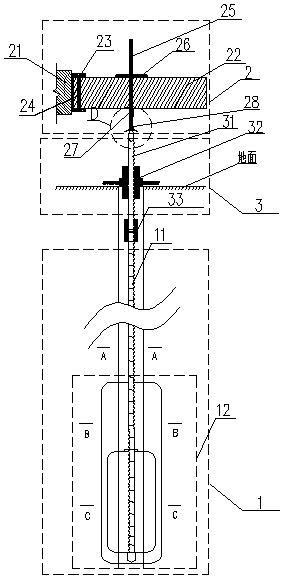
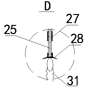
[0038] Specifically, as Figure 1-8 As shown, the device 100 includes: an expandable anchor body 1, an anti-floating unit 2 and an anti-sinking unit 3; wherein, the anti-sinking unit 3 includes a lead screw 31 and an anti-sinking controller 32, and the lead screw 31 The bottom of the body is fixedly connected with the ...


PUM


Abstract

The invention discloses equipment for resisting floating and sinking of a capsule under-reamed anchor. Floating and sinking of the capsule under-reamed anchor in a grouting process can be prevented bya guide screw connected with a capsule under-reamed anchor body, an anti-sinking controller on the guide screw, a steel beam and a fixing screw in an anti-floating unit as well as an anti-floating controller, a first clamping piece and a second clamping piece which are arranged on the fixing screw, so that height of the construction anchor exposed out of the horizon can be the expected height, welding or cutting is not needed any more, construction period is shortened, technological level of construction is increased, and materials and labor cost are saved. The invention further discloses a use method of the equipment for resisting floating and sinking of the capsule under-reamed anchor.

Description

technical field [0001] The invention relates to the technical field of construction engineering, in particular to a device for anti-floating and sinking of an expanding-type anchor and a method for using the device for anti-floating and sinking of an expanding-type anchor. Background technique [0002] At present, during the construction of the building, the expansion bolt will float up during the grouting process, and will sink after the grouting. The sinking anchor rod is uneven on the bottom surface of the foundation pit, which will have a certain impact on the later construction. If the length of the anchor rod exposed on the bottom surface of the foundation pit is short, another section of the anchor rod needs to be welded or nut-socketed. If the length of the anchor rod on the ground plane is long, a part needs to be cut off to meet the anchorage height of the anchor rod in the later construction. Among them, due to the different lengths of the anchor rods for welding ...

Claims


Application Information

Patent Timeline
Patent Type & Authority Applications(China)
IPC IPC(8): E02D5/80E02D31/12
Inventor 李留阳赵跃亭郭永弘陈佳雪杨巨万王学谦吴阿楠庞伟杰
Owner 山西冶金岩土工程勘察有限公司
Why Eureka
Try Eureka