A deep soil rapid collection device

A technology of deep soil and collection devices, applied in the direction of sampling devices, etc., can solve problems such as inability to collect soil, and achieve the effect of ensuring integrity

Active Publication Date: 2021-06-15
HEILONGJIANG ACAD OF FORESTRY
View PDF10 Cites 0 Cited by
  • Summary
  • Abstract
  • Description
  • Claims
  • Application Information

AI Technical Summary

Problems solved by technology

However, the device cannot collect deep soil

Method used


Image

  • A deep soil rapid collection device
  • A deep soil rapid collection device
  • A deep soil rapid collection device

Examples


specific Embodiment approach 1

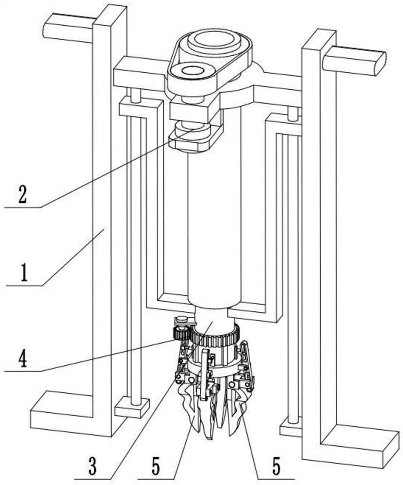
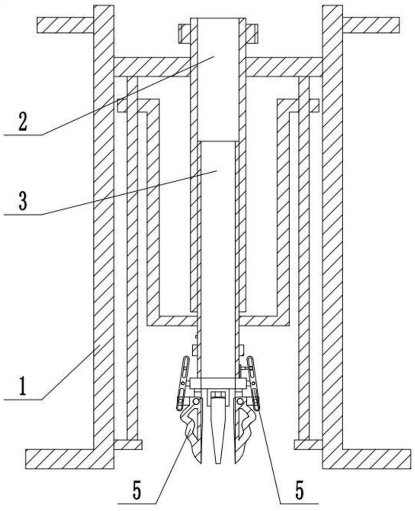
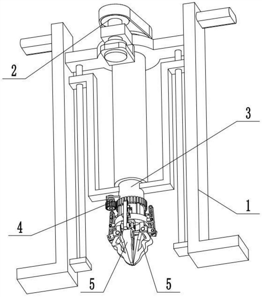
[0029] Combine below Figure 1-11 Description of this embodiment, a deep soil rapid collection device, including a sampling frame 1, a sampling depth control mechanism 2, a soil sampling cylinder assembly 3, a drill seat assembly 4 and a drill assembly 5, and the sampling depth control mechanism 2 is connected to The upper end of the sampling frame 1 and the two ends of the soil sampling cylinder assembly 3 are respectively slidingly fitted and connected to the two ends of the sampling frame 1, and the middle end of the soil sampling cylinder assembly 3 is connected to the sampling depth control mechanism 2 by threads, and the drill bit seat assembly 4 is connected to the lower end of the soil sampling cylinder assembly 3, and there are four drill bit assemblies 5, and the four drill bit assemblies 5 are evenly arranged around the lower end of the drill bit holder assembly 4. When the present invention is in use, the sampling frame 1 is placed on the geological surface to be s...

specific Embodiment approach 2

[0031] Combine below Figure 1-11 To illustrate this embodiment, the sampling rack 1 includes a horizontal frame plate 1-1, an L-shaped support plate 1-2, a handle bar 1-3, a base plate 1-4, and a guide rod 1-5; the horizontal frame plate The two ends of 1-1 are respectively fixedly connected to an L-shaped support plate 1-2, and the outer sides of the upper ends of the two L-shaped support plates 1-2 are respectively fixedly connected to a handle bar 1-3, and the two L-shaped support plates 1-2 The inner side of the lower end is fixedly connected to a base plate 1-4 respectively, and a guide rod 1-5 is fixedly connected to the two base plates 1-4 respectively, and the upper ends of the two guide rods 1-5 are fixedly connected to the horizontal frame plate 1-1 superior. When the sampling rack 1 is in use, hold the two handle bars 1-3 with both hands, and step on the lower ends of the two L-shaped support plates 1-2 with both feet, so as to ensure the stability of the device d...

specific Embodiment approach 3

[0033] Combine below Figure 1-11To illustrate this embodiment, the sampling depth control mechanism 2 includes an internally threaded sleeve 2-1, a depth control motor 2-2, a transmission shaft 2-3, a driving pulley 2-4, and a driven pulley 2-5; The upper end of the internally threaded sleeve 2-1 is rotatably connected to the middle end of the horizontal frame plate 1-1 through a bearing with seat, and the upper end of the internally threaded sleeve 2-1 is fixedly connected to the driven pulley 2-5, and the driven pulley 2 -5 is located at the upper end of the horizontal frame plate 1-1, the driven pulley 2-5 is connected with the driving pulley 2-4 through belt transmission, the driving pulley 2-4 is fixedly connected to the drive shaft 2-3, and the depth control The output shaft of the motor 2-2 is connected to the drive shaft 2-3 through a shaft coupling, and the depth control motor 2-2 is fixedly connected to the horizontal frame plate 1-1 through the motor frame. When t...


PUM


Abstract

The invention relates to a deep soil rapid collection device, which relates to the technical field of soil detection and includes a sampling frame, a sampling depth control mechanism, a soil sampling cylinder assembly, a drill bit seat assembly and a drill bit assembly. The beneficial technical effect is that the present invention is applicable to different geological types For soil collection, the soil in the deeper soil layer can be collected; when the soil sampling cylinder assembly penetrates into the soil to a sufficient depth, the lower end of the soil column is pinched off by controlling multiple drill bit assemblies, and the lower end of the soil column is Play the role of support to avoid the soil column being pulled away and broken when the soil column is taken out upward. The sampling depth control mechanism is connected to the upper end of the sampling frame, the two ends of the soil sampling cylinder assembly are respectively slidingly fitted and connected to the two ends of the sampling frame, the middle end of the soil sampling cylinder assembly is connected to the sampling depth control mechanism through threads, and the drill seat The assembly is connected to the lower end of the soil sampling cylinder assembly, and the four drill bit assemblies are uniformly arranged around the lower end of the drill bit seat assembly.

Description

technical field [0001] The invention relates to the technical field of soil detection, in particular to a deep soil rapid collection device. Background technique [0002] The existing patent No. is CN201720934631.X for a soil collection device. This utility model discloses a soil collection device, which includes a collection main rod, a fixed handle, a sampling limit plate, a soil sampling cylinder, a sampling cylinder cover, and multiple sampling cylinders. Punching teeth, multiple partition plate slots, movable handle, rotating bearing, drive motor, a pair of handle mounting brackets and multiple partition plates; the collection main rod is connected with a fixed handle and sampling limit plate, and the soil sampling cylinder passes through the sampling The cylinder cover is connected with the collection main rod. The sampling hole teeth are set at the lower end of the soil sampling cylinder. The partition plate is inserted into the soil sampling cylinder through the slot...

Claims


Application Information

Patent Timeline
Patent Type & Authority Patents(China)
IPC IPC(8): G01N1/08
Inventor 徐文煦刘长乐赵眉芳于沿泽张东来郑海峰蔡恒明庄立文贾丽楠叶梦园陈圣东孙长影刘霞
Owner HEILONGJIANG ACAD OF FORESTRY
Why Eureka
Try Eureka