
Inductance type magnetic nanometer material sensor and manufacturing method

A magnetic nanometer and magnetic nanoparticle technology, applied in the direction of material impedance, can solve problems such as equipment stoppage, mechanical failure, loss, etc., and achieve the effect of high discrimination, simple operation and convenient operation.

Inactive Publication Date: 2019-05-28
DALIAN MARITIME UNIVERSITY
View PDF5 Cites 4 Cited by
  • Summary
  • Abstract
  • Description
  • Claims
  • Application Information

AI Technical Summary

Problems solved by technology

Studies have shown that when the equipment is operating normally, metal abrasive particles will also be produced in the oil, but the size of the abrasive particles is small and the concentration is stable, usually between 10 μm and 20 μm, or even less than 5 μm; and once the equipment is abnormally worn When the abrasive particle size increases rapidly to 50 μm or even 100 μm, the concentration of abrasive particles will also increase accordingly. If the mechanical equipment is not repaired or the oil is replaced in time, the particle size and concentration will gradually increase, and when these abrasive particles enter When it hits the moving parts, it will cause mechanical failure, cause the equipment to stop running, and cause major losses

Method used


Image

  • Inductance type magnetic nanometer material sensor and manufacturing method
  • Inductance type magnetic nanometer material sensor and manufacturing method
  • Inductance type magnetic nanometer material sensor and manufacturing method

Examples


Embodiment

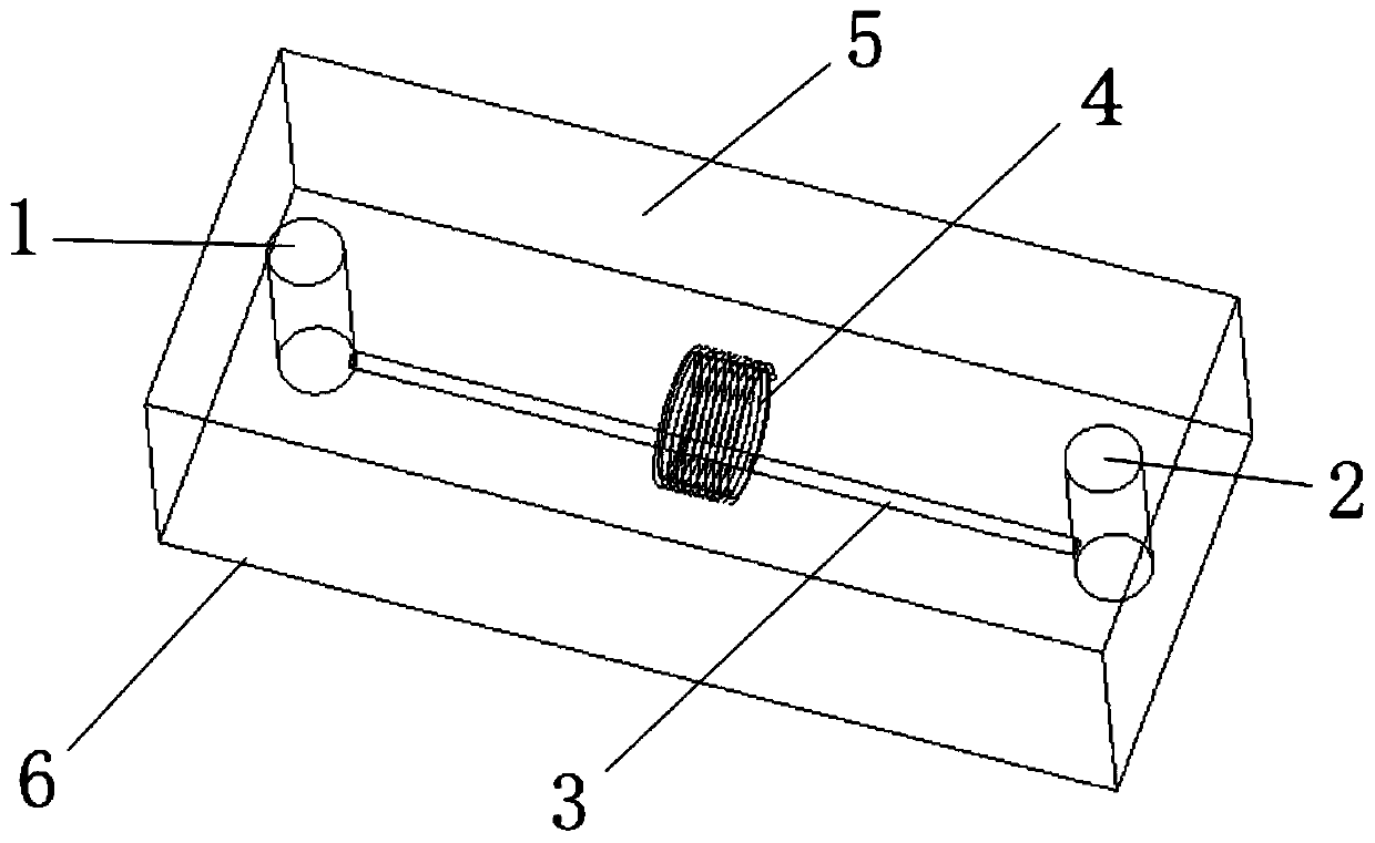
[0042] As a preferred embodiment of the present invention, the use process of the inductive magnetic nanomaterial sensor of the present invention is as follows:

[0043] Step 1: Transport the oil to be detected to the microchannel 3 through the oil inlet 1;

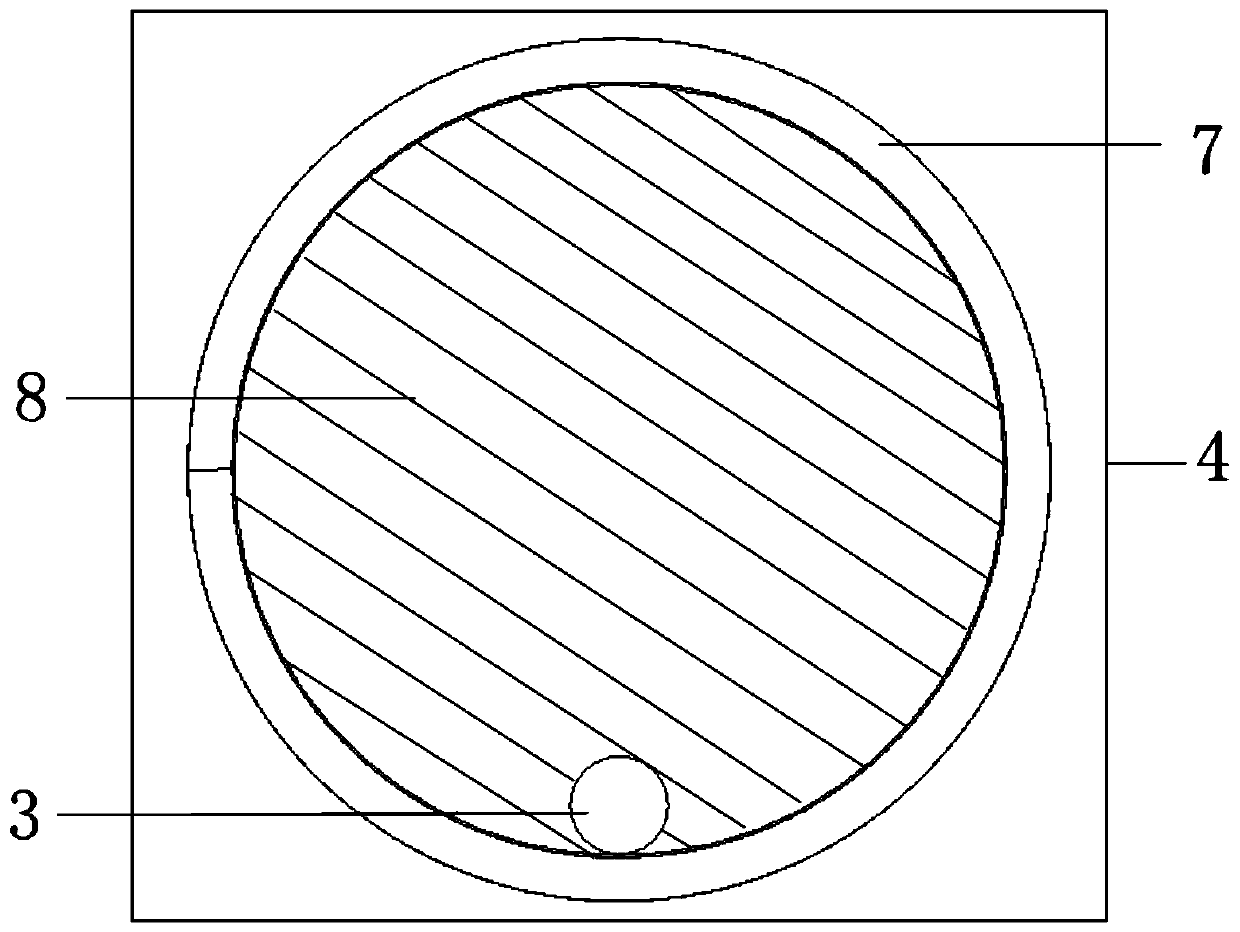
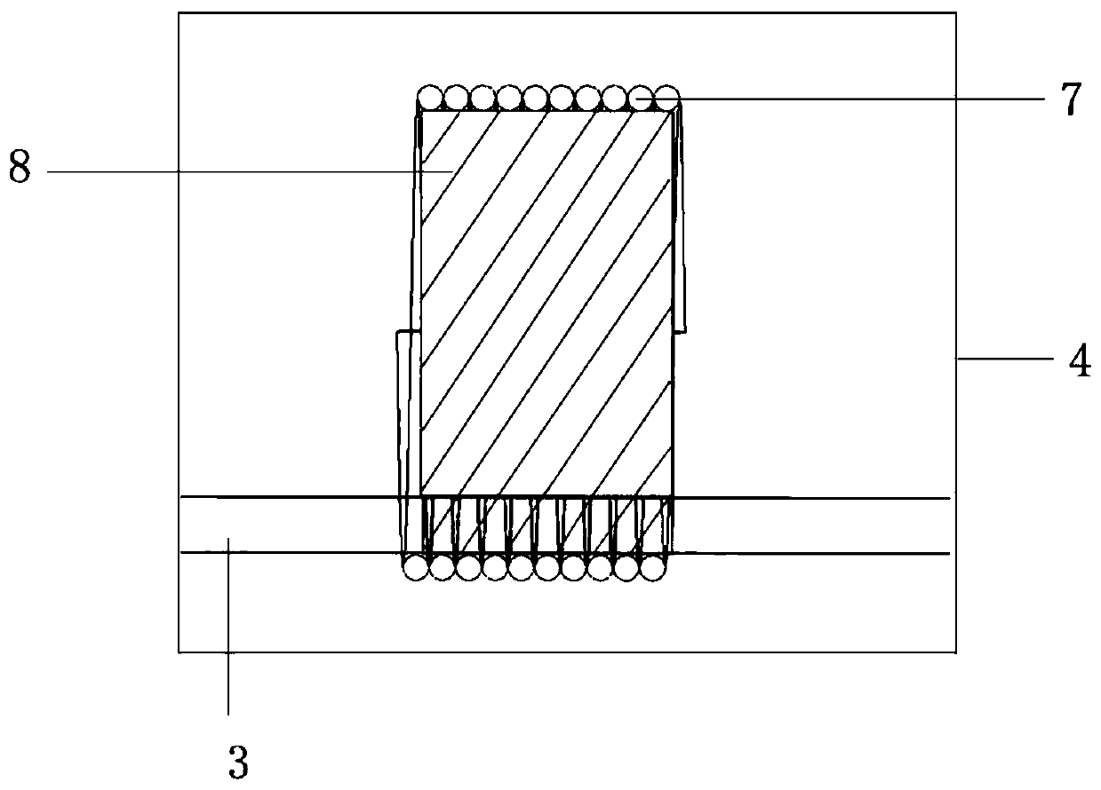
[0044] Step 2: The oil to be detected flowing through the sensing unit 4 is stimulated by a high-frequency signal through the sensing unit 4, and the detection of particle pollutants in the oil is distinguished and detected according to the detection results; Figure 4 As shown, when the sensor detects metal abrasive grains, the abrasive grains will be magnetized in the alternating magnetic field generated by the solenoid coil, and a new magnetic field will be generated after the ferromagnetic particles are magnetized. The direction is consistent with the coil magnetic field, and the detected inductance signal shows upward increase; such as Figure 5 As shown, when non-ferromagnetic particles pass through, the eddy curre...


PUM

PropertyMeasurementUnit
diameteraaaaaaaaaa

Abstract

The invention provides an inductance type magnetic nanometer material sensor and a manufacturing method. The sensor comprises a microfluidics detection chip and a sensing unit. The microfluidics detection chip comprises a glass substrate and a chip body arranged on the glass substrate. The chip body comprises a micro-channel arranged on the chip body and provided with an oil inlet in one end and an oil outlet in the other end. The sensing unit comprises a spiral pipe coil and a magnetic nanoparticle layer. The interior of the spiral pipe coil is completely attached to the magnetic nanoparticlelayer. According to the technical scheme, the problems that in a traditional inductance type method in the prior art, the detection precision is insufficient, detection timeliness is low and operation is difficult are solved.

Description

technical field [0001] The invention relates to the technical field of oil liquid detection, in particular to an inductive magnetic nanomaterial sensor and a manufacturing method. Background technique [0002] Particle pollutants in oil are the most important cause of hydraulic system failures. Being able to detect information about particle pollutants in oil is a reliable solution for fault diagnosis of equipment systems. Studies have shown that when the equipment is operating normally, metal abrasive particles will also be produced in the oil, but the size of the abrasive particles is small and the concentration is stable, usually between 10 μm and 20 μm, or even less than 5 μm; and once the equipment is abnormally worn When the abrasive particle size increases rapidly to 50 μm or even 100 μm, the concentration of abrasive particles will also increase accordingly. If the mechanical equipment is not repaired or the oil is replaced in time, the particle size and concentratio...

Claims


Application Information

Patent Timeline
Patent Type & Authority Applications(China)
IPC IPC(8): G01N27/02
Inventor 张洪朋白晨朝赵旭鹏曾霖虞子雷
Owner DALIAN MARITIME UNIVERSITY
Learn More