Unattended electronic invoice issuing system and device
A technology of electronic invoices and electronic bills, which is applied in the direction of receipt giving machines and instruments, can solve the problems of hard to realize paper invoice conversion as soon as possible, forged invoices, and weak invoice credibility, and solve the sudden problem of on-site fault lights , good social and economic benefits, convenient real-time and fast printing effect
- Summary
- Abstract
- Description
- Claims
- Application Information
AI Technical Summary
Problems solved by technology
Method used
Image
Examples
Embodiment 1
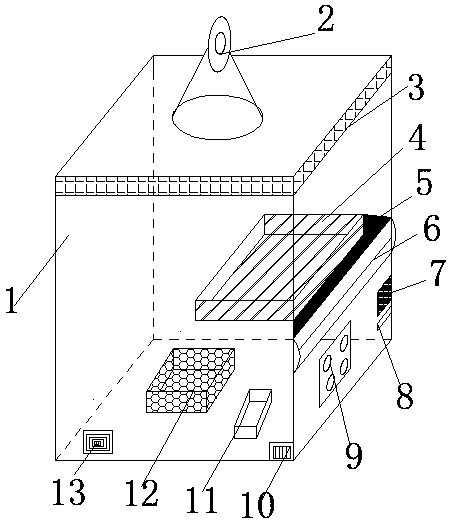
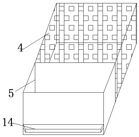
[0034] Embodiment 1: refer to Figure 2-3 , an unattended electronic invoice opening device, including a main body 1, a main controller 12 and a printer device 4, and also includes a seal sealing device 5 and an invoice transmission device 6; a monitoring device 2 is fixedly installed on the top of the main body 1, and the main body The four surfaces of the upper end of 1 are provided with heat dissipation meshes 3, and the lower surface of the main body 1 is respectively provided with an input panel 9, a card reading area 7 and a UnionPay port 8 from left to right, and an invoice printing device 4 is fixedly installed inside the main body 1 to print invoices. The front end of the device 4 is fixedly connected with a seal sealing device 5, the lower surface of the front end of the seal sealing device 5 is provided with an opening groove 14, the front end of the seal sealing device 5 is fixedly connected with an invoice transmission device 6, and the inner bottom surface of the ...
Embodiment 2
[0036] Embodiment 2: refer to Figure 4-6 , in conjunction with the basis of Embodiment 1, the seal stamping device 5 includes a protective frame 15, and the inner bottom surface of the protective frame 15 is fixedly connected with a plurality of sets of support rods 34, the top of the support rods 34 is provided with a sensing contact 33, and the upper end of the sensing contact 33 is provided with a Invoice slide plate 31, electromagnet A18 and electromagnetic controller 17 are fixedly installed on the left side of protective frame 15 from top to bottom, fixed frame body 19 is fixedly connected inside protective frame 15, and chute 23 is arranged at the upper right corner inside protective frame 15, The inside of the chute 23 is slidably connected with a slide bar 24, the lower end of the slide bar 24 is fixedly connected with an electromagnet B25, the electromagnet B25 matches the electromagnet A18, the front surface of the lower end of the slide bar 24 is fixedly connected ...
PUM
 Abstract
Description
Claims
Application Information
 - R&D
- Intellectual Property
- Life Sciences
- Materials
- Tech Scout
- Unparalleled Data Quality
- Higher Quality Content
- 60% Fewer Hallucinations
Browse by: Latest US Patents, China's latest patents, Technical Efficacy Thesaurus, Application Domain, Technology Topic, Popular Technical Reports.
© 2025 PatSnap. All rights reserved.Legal|Privacy policy|Modern Slavery Act Transparency Statement|Sitemap|About US| Contact US: help@patsnap.com


