

Heat dissipation device
A technology for heat sinks and chambers, applied in cooling/ventilation/heating transformation, etc., can solve the problems of complicated welding and assembly process, inconvenient installation and arrangement of electronic equipment, difficult piping arrangement, etc., so as to save labor costs and piping. Ease of layout, reducing the effect of assembly and soldering processes
- Summary
- Abstract
- Description
- Claims
- Application Information
AI Technical Summary
Benefits of technology
Problems solved by technology
Method used
Image

Examples
Embodiment Construction
[0036] Typical implementations embodying the features and advantages of the present application will be described in detail in the following description. It should be understood that the present application can have various changes in different embodiments without departing from the scope of the present application, and that the descriptions and illustrations therein are illustrative in nature and not limiting this application.
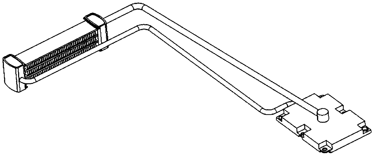
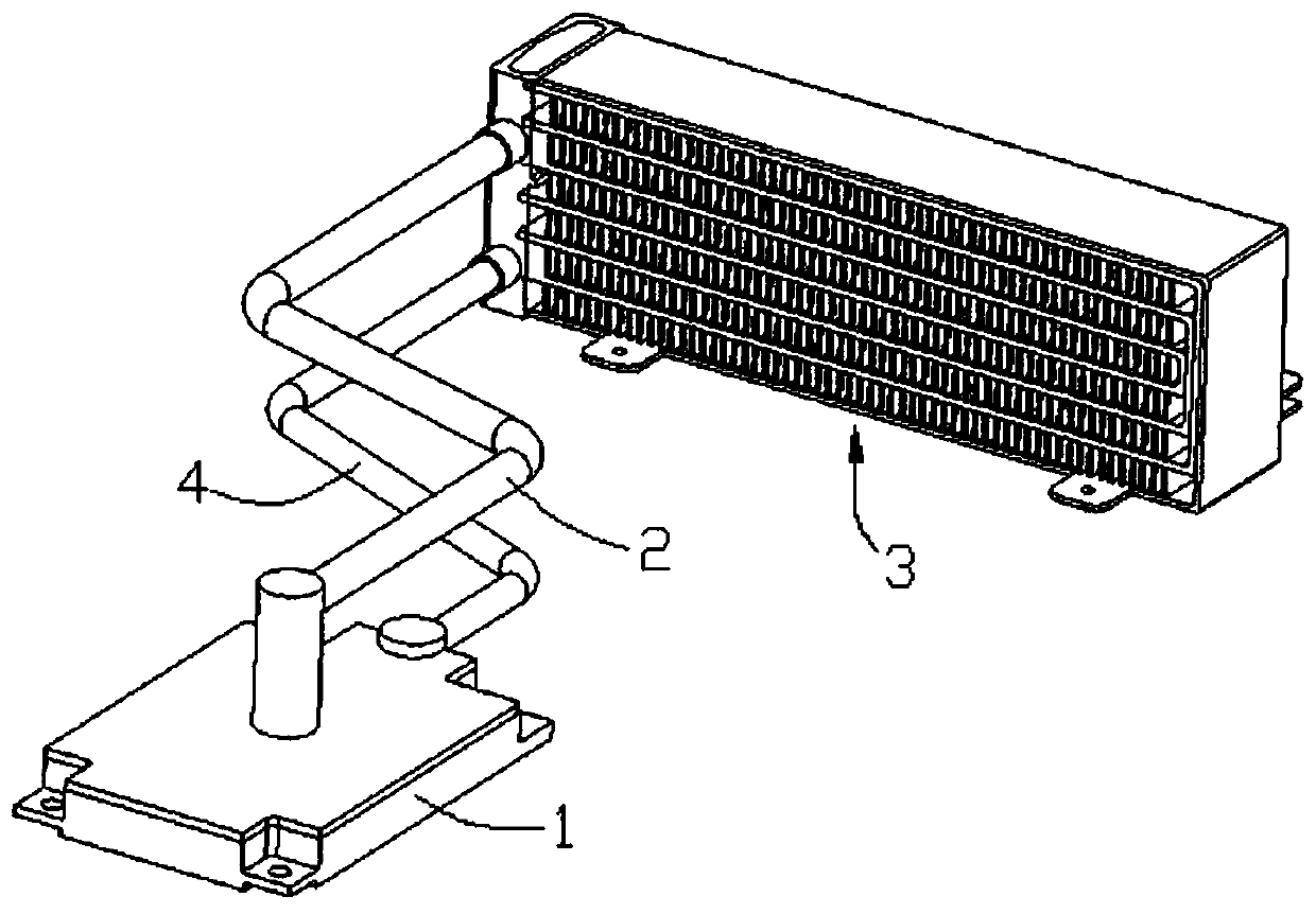
[0037] refer to Figure 2 to Figure 5 , the embodiment of the present application provides a heat dissipation device, including an evaporator 1 , a steam pipe 2 , a condenser 3 and a liquid pipe 4 .
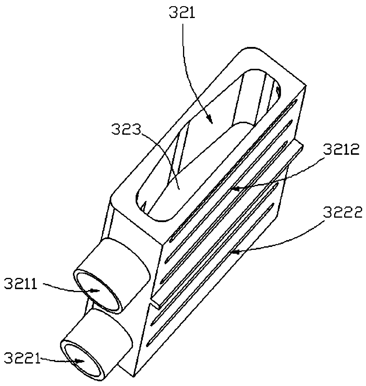
[0038] The condenser 3 is used to condense the gaseous working medium into a liquid working medium, and includes a flat tube 31 , a collector 32 , fins 33 and a protective frame 34 . Wherein, the collector body 32 is provided with an upper chamber 321 and a lower chamber (not shown in the figure), the upper chamber 321 is used to collect and accommodat...
PUM
 Abstract
Description
Claims
Application Information