
A placement rack for neurology

A neurology and placement rack technology, applied in the field of placement racks for neurology, can solve the problems of not being able to fix the patient's arm well, inconvenient for the patient to walk around, and cannot be adjusted, so as to improve the practical range, improve the use range, and have multiple functions Effect

Active Publication Date: 2021-07-23
JIAMUSI UNIVERSITY
View PDF0 Cites 0 Cited by
  • Summary
  • Abstract
  • Description
  • Claims
  • Application Information

AI Technical Summary

Problems solved by technology

[0003] The purpose of the present invention is to provide a placement rack for neurology to solve the problem that the existing placement rack proposed in the above-mentioned background technology has simple structure and single function, and medical equipment of different sizes cannot be placed on the same placement rack, which is inconvenient for patients to walk around. , to solve the problem of defecation, unable to fix the patient's arm well, to avoid the secondary injury caused by the patient's infusion site being pressed, and cannot be adjusted, so that the device for fixing the patient's arm can adapt to the use of different groups of people

Method used


Image

  • A placement rack for neurology
  • A placement rack for neurology
  • A placement rack for neurology

Examples


Embodiment 1

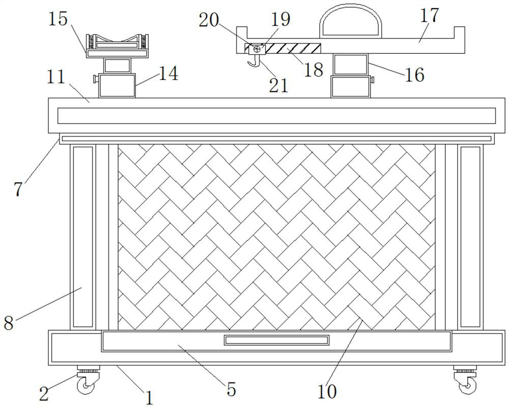
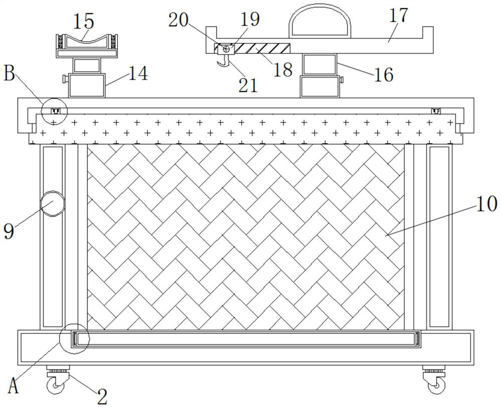
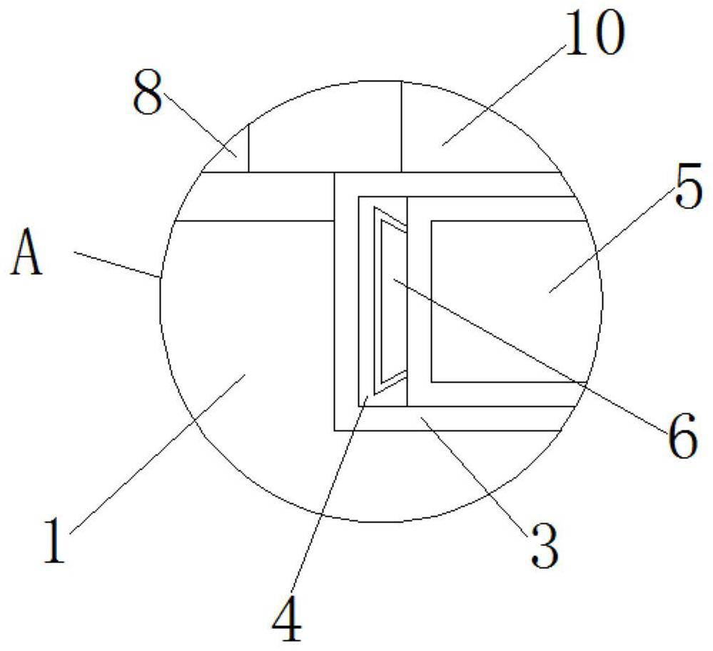
[0027] Example 1, such as figure 1 , 2 As shown in and 3, the four corners at the bottom of the base 1 are fixed with universal wheels 2, the inside of the base 1 is provided with a built-in cavity 3, and the inner walls of both sides of the built-in cavity 3 are fixed with built-in slide rails 4, and the built-in slide rails The built-in cavity 3 between 4 is provided with an extension board 5, and both sides of the extension board 5 are fixed with a built-in slider 6 that cooperates with the built-in slide rail 4, and the extension board 5 is pulled by the handle, and the built-in slide rail 4 and Under the interaction of the built-in slider 6, the extension plate 5 is pulled out from the built-in chamber 3, which is equivalent to increasing the length of the placement chamber 10, so that the device can place medical equipment of different sizes, and the structure is simple and practical.

[0028] The top of the base 1 is provided with a top plate 7, and the top plate 7 and...

Embodiment 2

[0032] Example 2, such as figure 1 , 2 , 5 and 6, when the patient needs infusion, first hang the infusion bottle on the hook 21, and then drive the pole 17 to extend upwards through the extension of the second telescopic rod 16 to reach a suitable height. When going to the toilet, the nurse can properly lower the second telescopic rod 16, and then the patient can move the device to the toilet under the action of the universal wheel 2, then unscrew the screw on the first telescopic rod 14 to adjust the first telescopic rod 14 When the height is appropriate, then tighten the screw on the first telescopic rod 14, and then place the arm at the infusion site on the arm placement device 15, which is simple and convenient, and is convenient for the patient to walk around.

Embodiment 3

[0033] Example 3, such as figure 1 , 2 , 5 and 6, when the patient uses the device, some medical equipment can be placed in the placement cavity 10, which is convenient to use, and the corresponding auxiliary equipment can also be placed in the placement cavity 10, and then the patient can use it when infusion Under the action of the second telescopic rod 16, the pole 17 is stretched, and then the medicinal solution is hung on the hook 21. The above-mentioned structure makes the overall structure of the device rich and realizes multiple functions.


PUM


Abstract

The invention discloses a neurology placing rack, comprising a base, an extension plate and a top plate, a top plate is arranged above the base, and the top plate and the base are connected by a support column, and both sides of the support column are A fixed rod is fixed, a placement cavity is fixed at the top of the base between the support columns, a rotating plate is arranged at the top of the top plate, and a cavity is arranged inside the rotating plate, and a pulley is symmetrically fixed at the bottom end of the rotating plate and a circular slide rail that cooperates with the pulley is fixed at one end of the top plate extending to the interior of the cavity. The multifunctional placement rack for neurology is rich in structure and has various functions, and can place medical equipment of different sizes on the same device, which improves the use range of the device. Patient privacy is guaranteed.

Description

technical field [0001] The invention relates to the technical field of medical equipment, in particular to a placement rack for neurology. Background technique [0002] At present, the placement rack in the hospital generally places some medical equipment, and then puts it in front of the patient's bed to detect or treat the patient. In addition, the placement rack has no other functions, which makes the device have a single function and a simple structure. And the size of each device is different, and the traditional racks are all targeted design, which can only adapt to the corresponding equipment, and cannot place devices of different sizes, which greatly reduces the scope of use of the rack, and patients generally need infusion , which requires a corresponding infusion stand, and the traditional infusion stand is not convenient for the patient to move, especially when the patient wants to solve the problem of defecation, he needs to be accompanied by the corresponding pe...

Claims


Application Information

Patent Timeline
Patent Type & Authority Patents(China)
IPC IPC(8): A61B50/22A61M5/14A61M5/52A61B50/26A61G12/00
Inventor 李培育孙淑波
Owner JIAMUSI UNIVERSITY
Learn More