Film-coating equipment for meniscus surface, and suction mechanical arm for film-coating component

A robotic arm and meniscus technology, which is applied to devices and coatings that apply liquid to the surface, can solve the problems of reducing the utilization rate of coating components, high energy consumption, and continuous production limitations, and achieves a high level of improvement. Coating film quality and product utilization rate, high film coating product quality, and the effect of preventing residual liquid from returning

Pending Publication Date: 2019-05-31
宁波甬安光科新材料科技有限公司
View PDF0 Cites 4 Cited by
  • Summary
  • Abstract
  • Description
  • Claims
  • Application Information

AI Technical Summary

Problems solved by technology

The main method of coating the film layer in the industry is still the mainstream of the physical method, such as the magnetron sputtering method, but the main disadvantage of the physical method is that it consumes a lot of energy and needs to be carried out in a vacuum environment.
The wet chemical method just overcomes this major shortcoming. It can be applied under normal pressure with low energy consumption. At present, there is a pull-up method, but it cannot be used to coat a single film. Continuous coating is also limited by equipment on a certain basis; spin coating Although the method can be used to coat a single film, it cannot be coated with a large-diameter uniform single film, and it cannot achieve continuous film coating.
Therefore, only meniscus coating technology can meet these requirements. However, it is still limited in continuous production. At present, there is no meniscus coating equipment for continuous production of high-quality coating products.
[0003] Another main defect of the coating film of the existing meniscus coating technology is that the retention of the coating liquid at the tail end of the coating film element will cause defects at the tail end of the coating film product, reducing the quality of the coating film and the utilization rate of the coating film element

Method used


Image

  • Film-coating equipment for meniscus surface, and suction mechanical arm for film-coating component
  • Film-coating equipment for meniscus surface, and suction mechanical arm for film-coating component
  • Film-coating equipment for meniscus surface, and suction mechanical arm for film-coating component

Examples


Embodiment 1

[0039] Embodiment 1 meniscus film coating equipment and its operation process

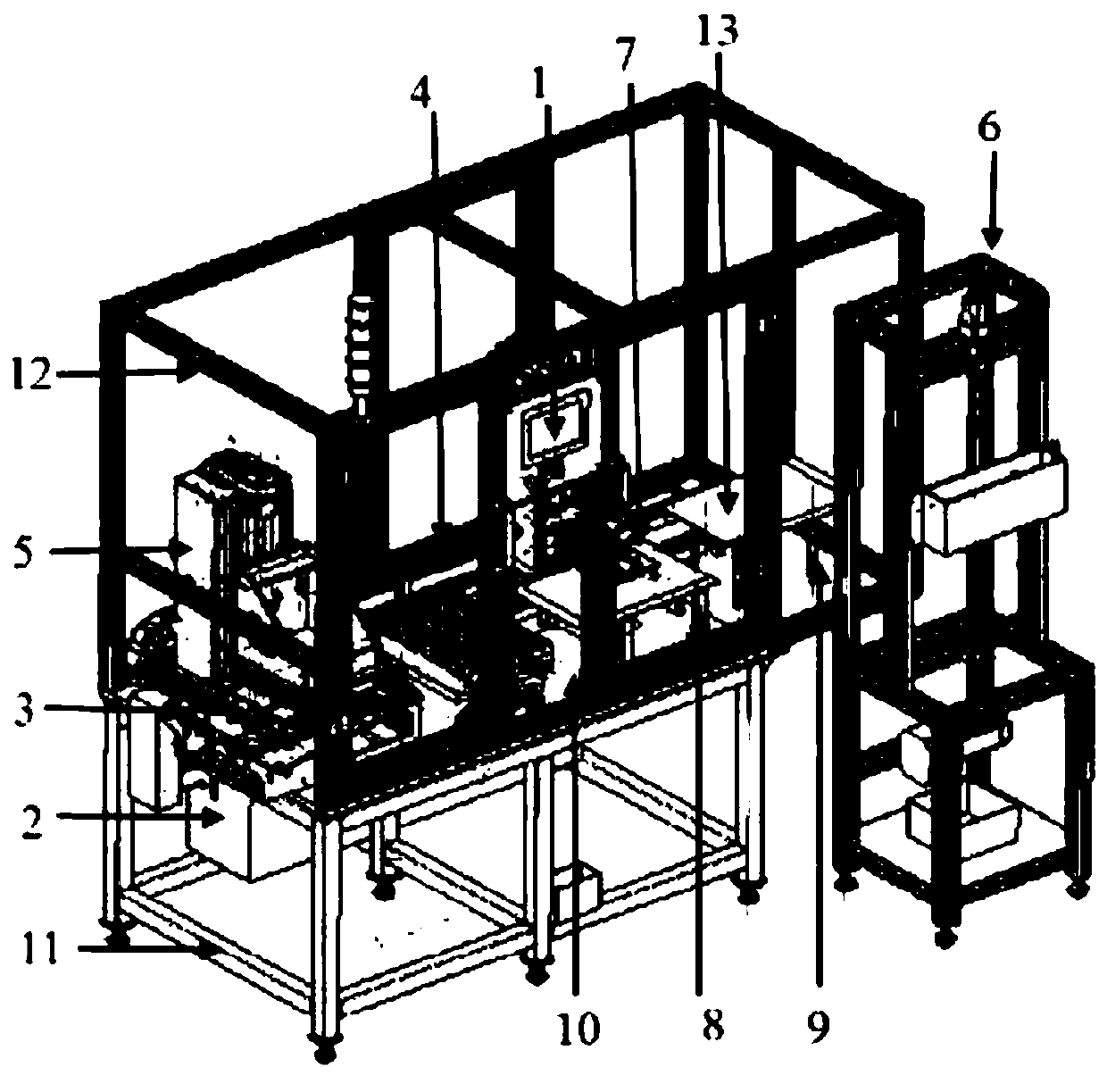
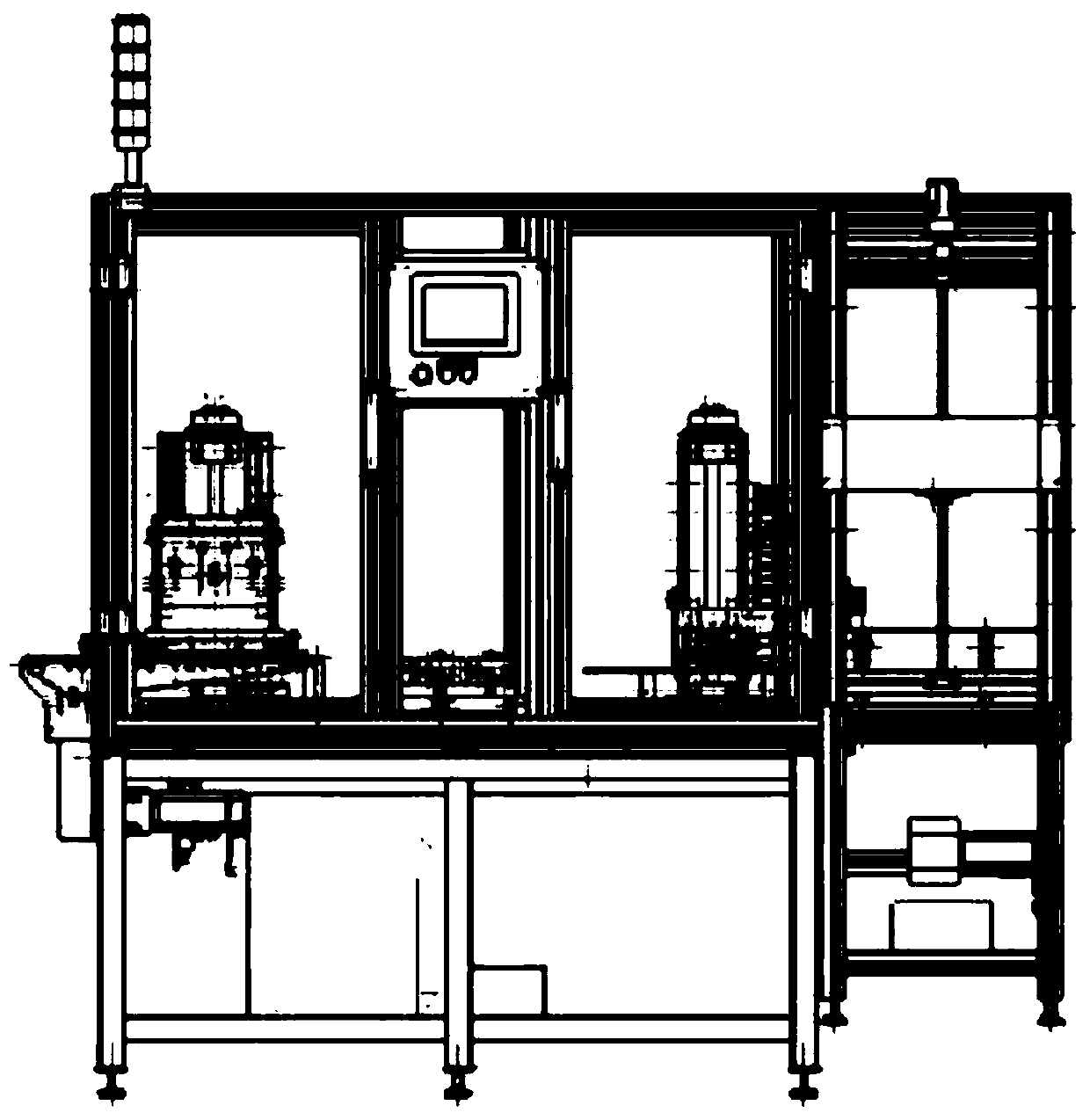
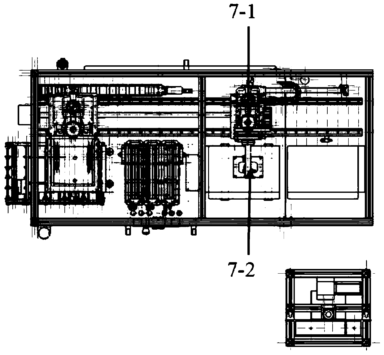
[0040] The three-dimensional structure of the meniscus gluing equipment of the present invention is as follows: figure 1 As shown, the front schematic diagram is shown in figure 2 As shown, the top view is as image 3 As shown, it can be understood from the figure that the main components of the meniscus film coating equipment of the present invention, Figure 4 It is the operation principle diagram of the meniscus film coating equipment, from which the film coating operation process of the meniscus film coating equipment of the present invention can be clearly understood.

[0041] The above-mentioned meniscus film coating equipment includes a central control panel (1), a PCL control cabinet (2), a coating film component positioning loading table (3), a linear motor drive guide rail (4), a coating film component suction mechanical arm (5 ), Glue supply device (6), film-coating element overturni...

Embodiment 2

[0053] Embodiment 2 Coating element suction mechanical arm with anti-swinging edge effect

[0054] The three-dimensional schematic diagram, the front schematic diagram and the top view of the coating element absorbing mechanical arm with the anti-shake effect of the present invention are respectively as follows Figure 5-7 As shown, it mainly includes the following important components: film coating element walking robot arm (5-2), drainage elastic clip (5-2-2), suction cup (5-2-1).

[0055] Such as Figure 6As shown, the elastic clip (5-2-2) at the tail end of the coating element and the contact part of the coating element (13) have a concave structure, and only the bottom edge coincides with the coating surface of the coating element, while the coating element The upper surface does not touch any parts, so the residual liquid on the coating surface of the coating element will not flow back to the upper surface of the coating element to affect the effect and quality of the c...

Embodiment 3

[0057] Example 3 Glue spraying device with leveling function [HJ1]

[0058] The structure of the glue spraying device with leveling effect of the meniscus glue coating equipment of the present invention is as follows: Figure 8 shown.

[0059] The leveling device (6-2-5) includes an adjustment wheel (6-2-5-1), a leveling piece (6-2-5-2) and a support base (6-2-5-3). Wherein the connection between each component of the leveling device and the glue spraying device can be clearly reflected, the leveling device not only has the main leveling function, but also is the main supporting part for fixing the glue spraying device, the spraying glue The glue device is fixed on the equipment support plate by means of the support base of the leveling component and the support base of the rotating shaft of the leveling component. The leveling member mainly relies on the relative movement between the leveling wheel and the leveling member to realize the leveling of the glue spraying device....


PUM


Abstract

The invention discloses film-coating equipment for a meniscus surface, and a suction mechanical arm for a film-coating component, and belongs to the field of continuous production for leveled coated films. The coating equipment for the meniscus surface comprises a central control panel (1), a PLC control cabinet (2), a location sheet-loading table (3) for the film-coating component, a linear motordrive guide rail (4), the suction mechanical arm (5) for the film-coating component, a glue supply device (6), an overturning sheet-unloading table (7) for the film-coating component, an overturningtransition frame (8) for the film-coating component, a sheet-unloading placement frame (9) for the film-coating component, an equipment support table (10), an equipment support (11), and an equipmentdustproof cover (12). The equipment is capable of forming a continuous and stable glue solution coating layer for the meniscus surface, has an anti-residual function, and is capable of completing continuous production for high-quality single-sided multilayer film-coated products or double-sided heterogeneous film-coated products.

Description

technical field [0001] The invention belongs to meniscus film coating equipment for continuous production of single-sided multi-layer or double-sided heterogeneous coating film products, and belongs to the field of continuous production of advection coating films. Background technique [0002] At present, many large-caliber optical switching devices, optical lenses, optical displays, etc. need to be coated with special coatings to change the surface properties, such as changing the light transmittance (anti-reflection coating or high-reflection coating), changing the abrasion resistance and prolonging the use of materials. Some require a single-sided multilayer film, and some require a double-sided heterogeneous film. The main method of coating the film layer in the industry is still the mainstream low-level physical method, such as the magnetron sputtering method, but the main disadvantage of the physical method is that it consumes a lot of energy and needs to be carried ou...

Claims


Application Information

Patent Timeline
IPC IPC(8): B05C5/02B05C11/10B05C13/02
CPCY02P70/10
Inventor 胡文杰
Owner 宁波甬安光科新材料科技有限公司
Why Eureka
Try Eureka