mold

A mold and template technology, applied in the direction of forming tools, manufacturing tools, feeding devices, etc., can solve the problems of increasing processing procedures, long processing time, increasing production costs, etc., and achieve the effect of reducing production costs and shortening processing time

Active Publication Date: 2020-03-24
田沃土
View PDF6 Cites 0 Cited by
  • Summary
  • Abstract
  • Description
  • Claims
  • Application Information

AI Technical Summary

Problems solved by technology

[0004] The existing processing of the workpiece requires two steps and two sets of different molds. On the one hand, the processing process is increased and the processing time is longer. On the other hand, the two sets of molds will generate additional costs and increase the production cost.

Method used


Image

  • mold
  • mold
  • mold

Examples


Embodiment Construction

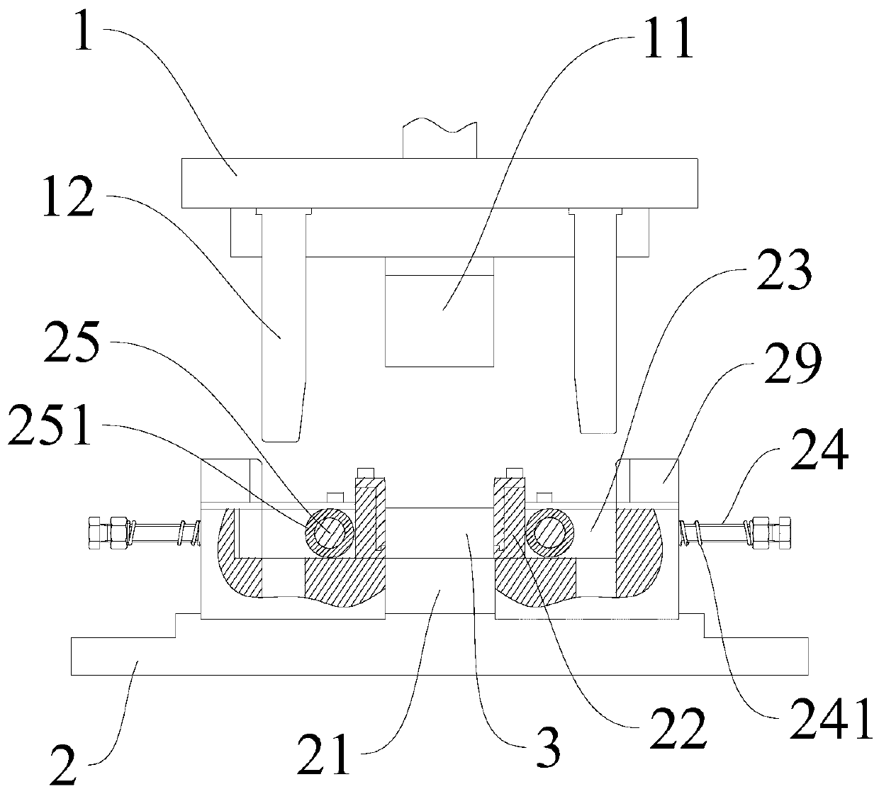
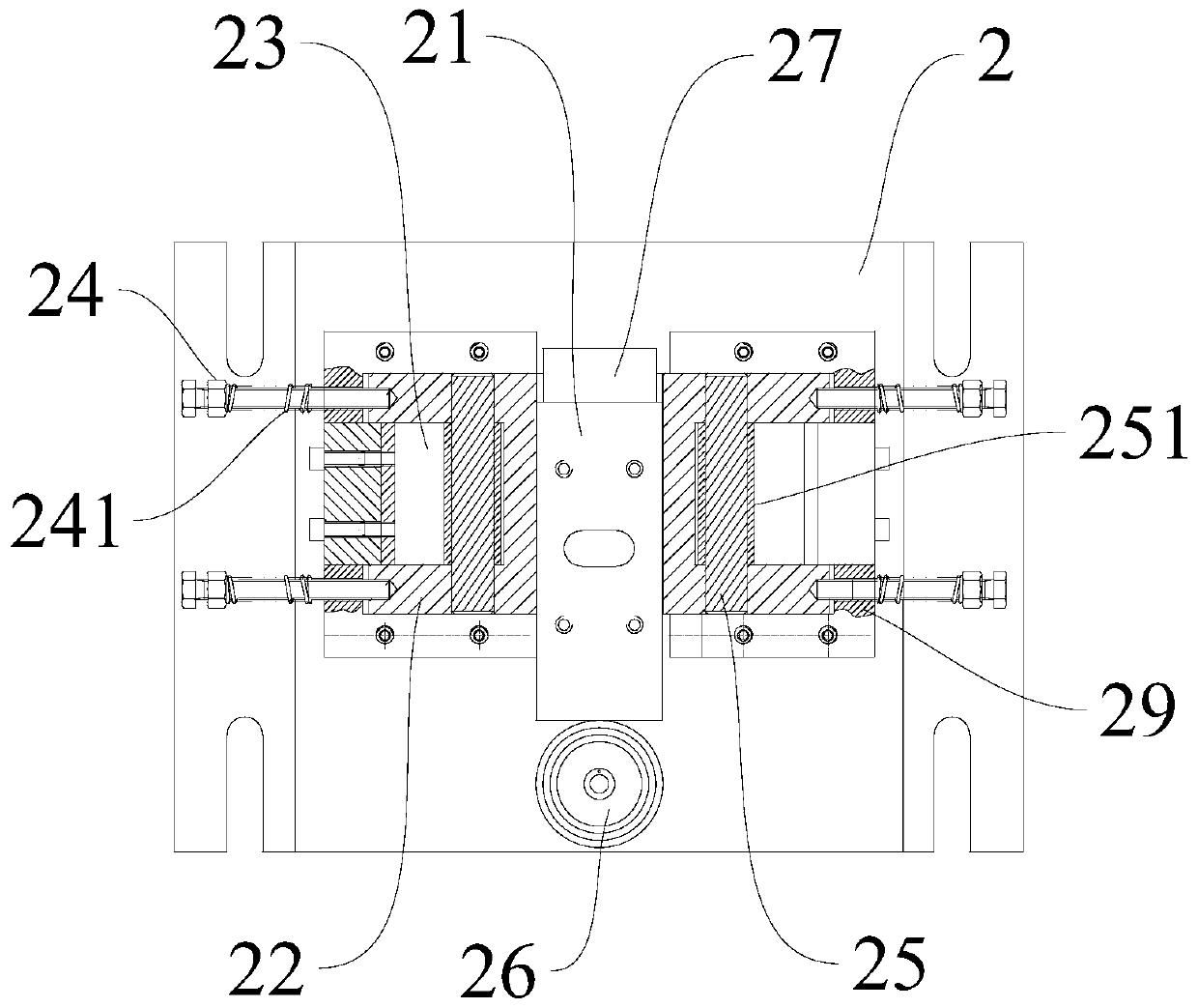
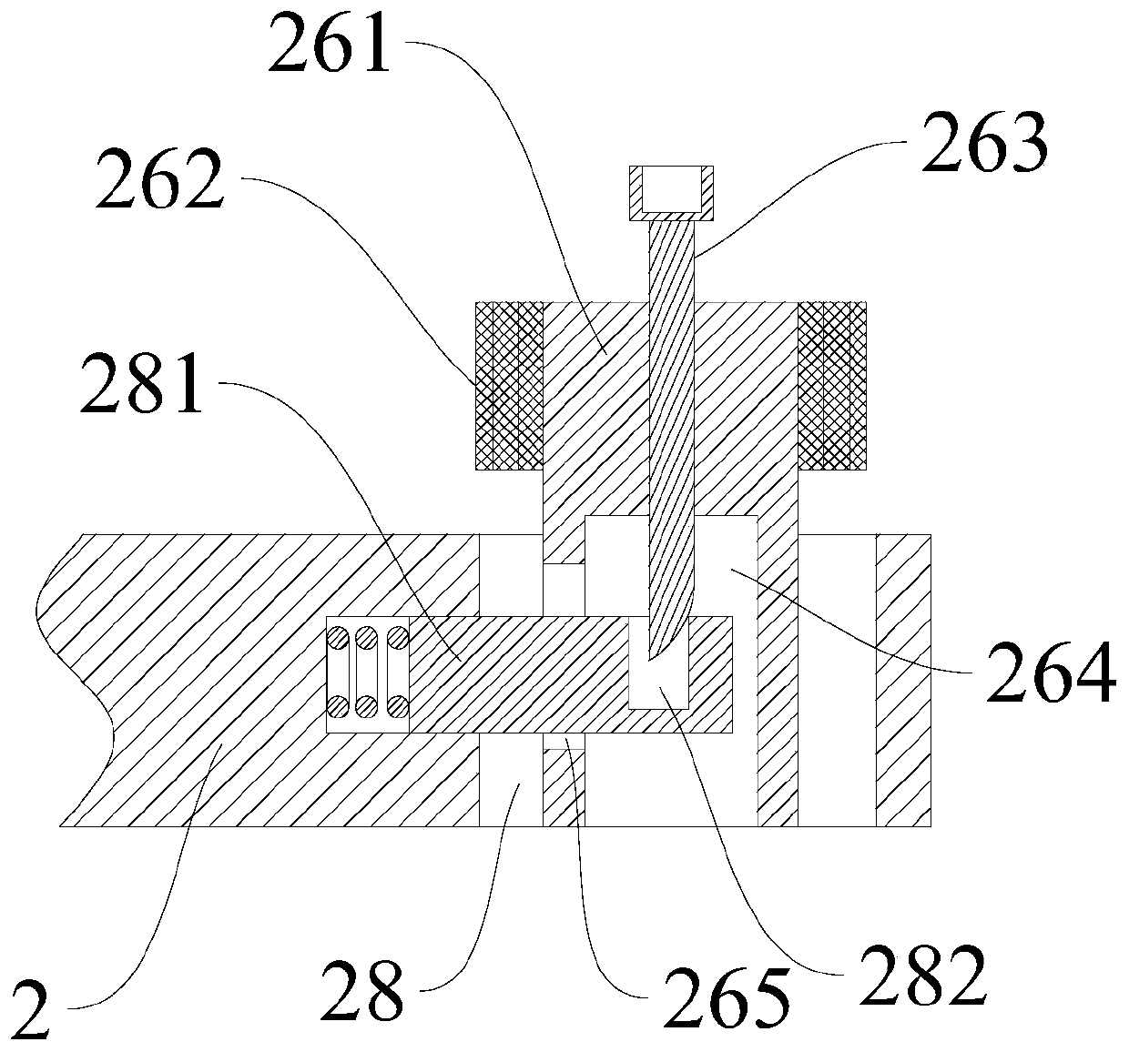
[0028] In order to make the purpose, features and advantages of the present invention more obvious and understandable, the specific implementation manners of the present invention will be described in detail below in conjunction with the accompanying drawings. Several embodiments of the invention are shown in the drawings. However, the present invention can be embodied in many different forms and is not limited to the embodiments described herein. Rather, these embodiments are provided so that the disclosure of the present invention will be thorough and complete.

[0029] It should be noted that when an element is referred to as being “fixed on” another element, it may be directly on the other element or there may be an intervening element. When an element is referred to as being "connected to" another element, it can be directly connected to the other element or intervening elements may also be present. As used herein, the terms "vertical," "horizontal," "left," "right," "u...


PUM

PropertyMeasurementUnit
angleaaaaaaaaaa

Abstract

The invention discloses a die for machining a workpiece. An upper template and a lower template are included and are oppositely provided with an upper die forming block and a lower die forming block correspondingly. The lower die forming block is used for containing the workpiece, the parts, located on the two sides of the lower die forming block, of the lower template are provided with transverseextrusion blocks, and the transverse extrusion blocks are provided with guiding grooves. The upper template is provided with wedge-shaped blocks corresponding to the guiding grooves. When the wedge-shaped blocks downwards stretch into the guiding grooves to slide, the two transverse extrusion blocks oppositely move. When the upper die forming block conducts downward pressing, the wedge-shaped blocks can move along with the upper die forming block, meanwhile, the wedge-shaped blocks can push the transverse extrusion blocks to move, the die can achieve workpiece width finishing and forming simultaneously or sequentially, additional adoption of other dies is not needed, the machining time is shortened, and the production cost is reduced.

Description

technical field [0001] The invention relates to the technical field of stamping, in particular to a mold. Background technique [0002] With the advancement of science and technology and the improvement of people's living standards, people's demand for products is also increasing, and manufacturers need to improve production efficiency. [0003] The stamping or punching of the product usually uses a mold with a specified shape. The existing stamping process is generally divided into two steps: the first step is to use a punch and a mold to trim the width of the workpiece; the second step is to use another punch and a mold Carry out radian forming on the workpiece. Using the above steps, the workpiece can be processed into the specified size and shape. [0004] The existing processing of the workpiece requires two steps and two sets of different molds. On the one hand, the processing procedure is increased and the processing time is longer. On the other hand, the two sets o...

Claims


Application Information

Patent Timeline
Patent Type & Authority Patents(China)
IPC IPC(8): B21D37/10B21D37/12B21D43/00B21D28/14
Inventor 田沃土
Owner 田沃土
Why Eureka
Try Eureka