Precise hydraulic clamp

A hydraulic fixture and precision technology, which is applied in the direction of manufacturing tools, grinding workpiece supports, grinding machines, etc., can solve the problems that the length and size of parts are difficult to control precisely, the eccentricity of parts is difficult to ensure, and the end face grinding is difficult to achieve, so as to achieve uniform force , prevent hydraulic oil leakage, eliminate the effect of precision deviation

Pending Publication Date: 2019-05-31
广州德马威工业装备制造有限公司
View PDF1 Cites 3 Cited by
  • Summary
  • Abstract
  • Description
  • Claims
  • Application Information

AI Technical Summary

Problems solved by technology

[0002] When traditional thin-walled cylindrical parts are precision-ground, taper rods are generally used to wedge the inner hole. Due to the influence of the inner hole and tolerances, the axial position of the part clamped on the grinding machine changes greatly, resulting in frequent resetting of the grinding wheel position. , and it is difficult to grind the end faces at the same time, and it is difficult to precisely control the length and dimension of the parts. The processing of eccentric cylinders and thin-walled cylindrical parts cannot meet the increasingly high precision requirements of parts for traditional fixtures.
[0003] For example, the patent application with the application number 201410585694.X discloses a fixture for fine grinding of the outer circle of an eccentric cylinder and a processing method using the same, which does not require center adjustment, fast clamping parts, and uniform force on the parts; The positioning pin is stuck in the groove of the cylinder for installation, the stress is concentrated on one side of the positioning pin, the clamping force is inconsistent, the force is uneven during processing, and it is difficult to ensure the eccentricity of the part, the coaxiality of the inner and outer circles, and the perpendicularity between the end surface and the inner and outer circles and parallelism of inner and outer circles

Method used


Image

  • Precise hydraulic clamp
  • Precise hydraulic clamp
  • Precise hydraulic clamp

Examples


Embodiment 1

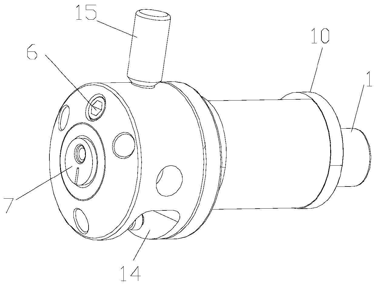
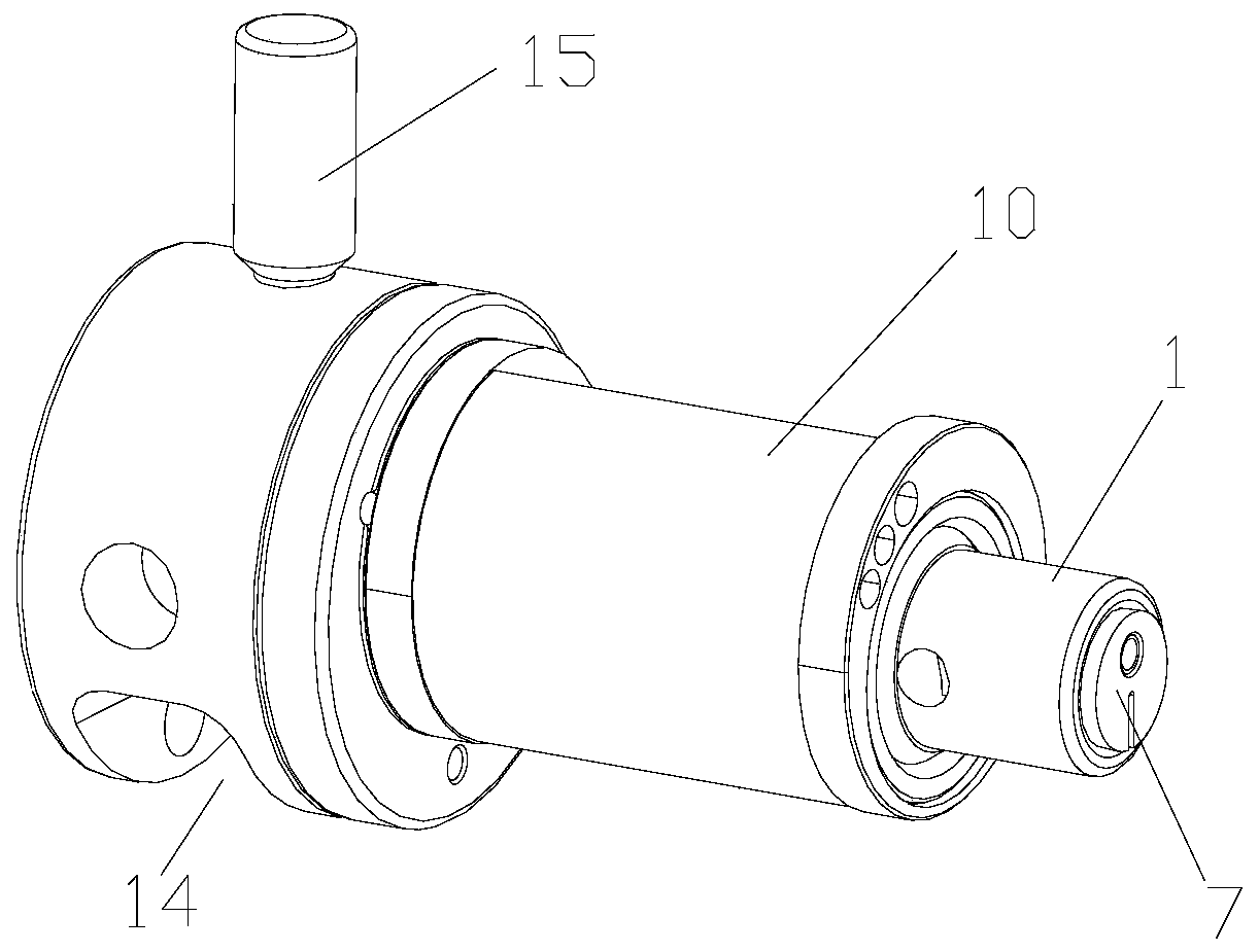
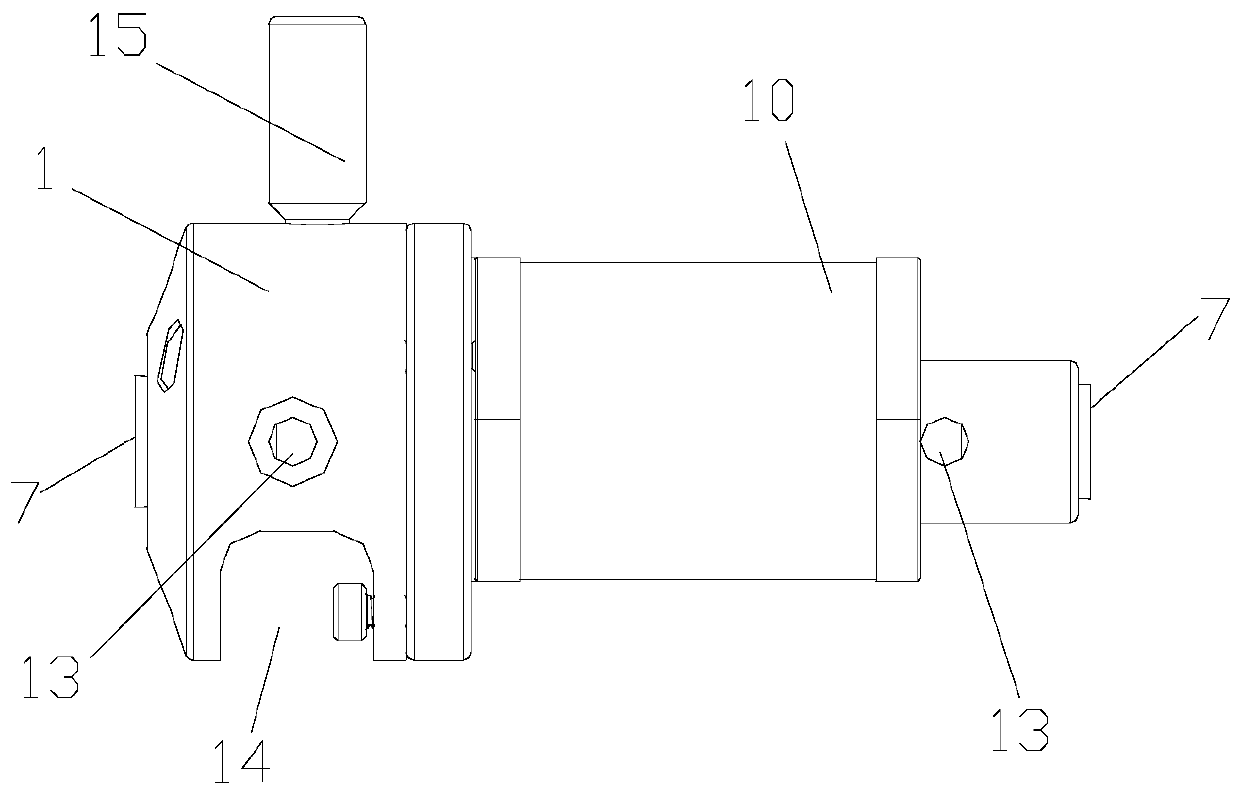
[0036] Such as figure 1 , 2 A precision hydraulic fixture shown in, 3 and 4, comprising: a mandrel 1, which is connected to the rotary table of the grinding machine spindle;

[0037] The expansion sleeve 2 is sleeved on the outer edge of the mandrel 1 and is used to fix the workpiece 10. There is an expansion space 3 between the expansion sleeve 2 and the mandrel 1, and the expansion sleeve 2 is expanded by injecting oil into the expansion space 3 to apply pressure to it. Work piece 10 is fixed;

[0038] The booster flow passage 4 is arranged in the mandrel 1 and communicates with the expansion space 3. The front end of the booster flow passage 4 is provided with a pressurized piston 5 communicating with the expansion space 3.

[0039] In this embodiment, the pressurized piston 5 is installed after the oil is injected, and the structure is simpler.

[0040] Among them, the expansion sleeve 2 expands uniformly, and evenly applies pressure to the 10 peripheral edges of the workpiece, to...

Embodiment 2

[0042] Such as figure 1 , 2 A precision hydraulic fixture shown in, 3 and 4, comprising: a mandrel 1, which is connected to the rotary table of the grinding machine spindle;

[0043] The expansion sleeve 2 is sleeved on the outer edge of the mandrel 1 and is used to fix the workpiece 10. There is an expansion space 3 between the expansion sleeve 2 and the mandrel 1, and the expansion sleeve 2 is expanded by injecting oil into the expansion space 3 to apply pressure to it. Work piece 10 is fixed;

[0044] The booster flow passage 4 is arranged in the mandrel 1 and communicates with the expansion space 3. The front end of the booster flow passage 4 is provided with a pressurized piston 5 communicating with the expansion space 3.

[0045] Among them, the expansion sleeve 2 expands uniformly and uniformly applies pressure to the 10 circumference of the workpiece to ensure that the clamping force is consistent during the processing, and the force is uniform during processing, to ensure th...


PUM


Abstract

The invention relates to a precise hydraulic clamp. The precise hydraulic clamp comprises a mandrel, an expansion sleeve and a pressurization flow channel. The mandrel is connected with a grinding machine spindle turntable or a center. The expansion sleeve sleeves the outer edge of the mandrel and is used for fixing a workpiece. An expansion space is formed between the expansion sleeve and the mandrel. The expansion space is subjected to oil filling and pressurizing to expand the expansion sleeve, so that the expansion sleeve and the workpiece can be fixed together. The pressurization flow channel is arranged in the mandrel and communicates with the expansion space. A pressurization piston communicating with the expansion space is arranged at the front end of the pressurization flow passage. The precise hydraulic clamp is consistent in clamping force all the time.

Description

Technical field [0001] The invention relates to the field of clamping equipment for thin-walled cylindrical parts or eccentric cylinders, in particular to a precision hydraulic clamp. Background technique [0002] Traditional thin-walled cylindrical parts generally use taper rods to wedge the inner hole when precision grinding the outer circle. Affected by the inner hole and tolerances, the axial position of the part clamped on the grinder changes greatly, resulting in frequent resetting of the grinding wheel position , And it is difficult to grind the end faces at the same time, and it is difficult to precisely control the length of the parts. The processing of eccentric cylinders and thin-walled cylindrical parts cannot meet the increasingly high accuracy requirements of parts for traditional fixtures. [0003] For example, the patent application with the application number 201410585694.X discloses a jig for eccentric cylinder external precision grinding that does not require cen...

Claims


Application Information

Patent Timeline
Patent Type & Authority Applications(China)
IPC IPC(8): B24B41/06B24B41/00B24B5/01
Inventor 袁荣志
Owner 广州德马威工业装备制造有限公司
Why Eureka
Try Eureka