Supercharge Your Innovation With Domain-Expert AI Agents!

An injection mold for PE pipe production

A technology for injection molds and injection tanks, which can be used in household appliances, other household appliances, applications, etc. It can solve the problems of accumulation of injection molding liquid, lack of guide parts, and pollution of the injection molding environment, so as to improve the efficiency of mold taking and avoid local accumulation. , to ensure clean effect

Active Publication Date: 2020-12-04
台州新凯科技服务有限公司
View PDF6 Cites 0 Cited by
  • Summary
  • Abstract
  • Description
  • Claims
  • Application Information

AI Technical Summary

Problems solved by technology

Among them, injection molds are used in the production process of PE pipes. However, the existing injection molds for PE pipe production lack waste gas collection and purification devices, so that the waste gas generated during the injection molding process of PE pipes cannot be treated in time, causing pollution. In the injection molding environment, and limited by the structure of the existing injection mold for PE pipe production during the mold taking process, the mold can only be disassembled by removing the bolts to complete the mold taking operation, and the mold taking efficiency is relatively low. In addition, it lacks the design of the guide parts, so that the local accumulation of injection liquid often occurs during the injection molding process, thereby reducing the quality of injection molding. Therefore, an injection mold for PE pipe production is urgently needed to solve the existing problems.

Method used


Image

  • An injection mold for PE pipe production
  • An injection mold for PE pipe production
  • An injection mold for PE pipe production

Examples


Embodiment Construction

[0029] The present invention will be further described below in conjunction with accompanying drawing:

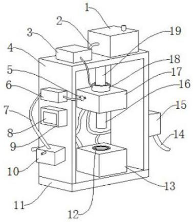
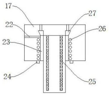
[0030] Such as Figure 1-Figure 7As shown, an injection mold for PE pipe production includes a base plate 11, an upper mold base 17 and a lower mold base 13. There is an injection molding groove 29, an annular clamping groove 12 is arranged on one side of the injection molding groove 29, and cooling water pipes 3 28 are spirally distributed in the lower mold base 13 close to the injection molding groove 29, and the lower mold base 13- The side is welded with a bracket 4, the side wall of the bracket 4 is provided with a PLC controller 9, the middle part of the side wall of the PLC controller 9 is provided with an operation panel 8, and the upper side of the PLC controller 9 is provided with an exhaust fan 6, The lower part of the PLC controller 9 is provided with a purification box 10, the input end and the output end of the exhaust fan 6 are provided with a trachea 7, and...


PUM


Abstract

The invention discloses an injection mold for PE pipe production. A bottom plate, an upper mold base and a lower mold base are included. The lower mold base is welded to the middle portion of the upper end of the bottom plate. An injection molding groove is formed in the middle portion of the upper end of the lower mold base, and an annular clamping groove is formed in one side of the injection molding groove. The injection mold has the beneficial effects that through design of an exhaust fan, an air pipe, an air gathering hood and a purification box, waste gas generated in the injection molding process can be effectively treated, and cleanliness of the injection molding environment is ensured; through the design of an electric push rod, separation of the upper mold base and the lower moldbase is more convenient, separation can be conducted without a bolt detachment manner, and the mold taking efficiency is greatly improved; and through the design of a liquid injection ring pipe and annularly-distributed injection molding pipes, injection molding liquid can evenly fall down along a cavity at the same time in the injection molding process, local accumulation of the injection molding liquid is avoided, and the injection molding quality is improved.

Description

technical field [0001] The invention relates to the technical field of pipe fitting molds, in particular to an injection mold for PE pipe production. Background technique [0002] PE pipe is a pipe fitting made of polyethylene plastic, which has excellent resistance to most domestic and industrial chemicals, and is often used as a substitute for steel pipes and iron pipes in various fields of people's lives. Among them, injection molds are used in the production process of PE pipes. However, the existing injection molds for PE pipe production lack waste gas collection and purification devices, so that the waste gas generated during the injection molding process of PE pipes cannot be treated in time, causing pollution. In the injection molding environment, and limited by the structure of the existing injection mold for PE pipe production during the mold taking process, the mold can only be disassembled by removing the bolts to complete the mold taking operation, and the mold ...

Claims


Application Information

Patent Timeline
Patent Type & Authority Patents(China)
IPC IPC(8): B29C45/26B29C45/73B29C45/17B29L23/00B29K23/00
Inventor 王甲亮
Owner 台州新凯科技服务有限公司
Features
  • R&D
  • Intellectual Property
  • Life Sciences
  • Materials
  • Tech Scout
  • Unparalleled Data Quality
  • Higher Quality Content
  • 60% Fewer Hallucinations
Learn More