
Air conditioner of passenger vehicle

A passenger car and air-conditioning technology, applied to vehicle parts, air handling equipment, heating/cooling equipment, etc., can solve the problems of increasing driving wind resistance, poor heating effect, increasing the height of the vehicle, etc., to reduce the probability of debris entering , Improve space utilization and reduce vehicle height

Active Publication Date: 2019-05-31
GREE ELECTRIC APPLIANCES INC
View PDF8 Cites 3 Cited by
  • Summary
  • Abstract
  • Description
  • Claims
  • Application Information

AI Technical Summary

Problems solved by technology

[0003] The roof-mounted air conditioner is installed on the roof of the bus. The condensing return air and the air outlet are located on the roof. Rainy and snowy days are likely to affect the work of the external fan, and it is easy to enter debris and cause failure.
Since the air outlet of the evaporator is located on the top of the interior compartment, the hot air is not easy to blow downwards. In winter, the upper part of the compartment is hot and the lower part is cold, and the heating effect is poor.
Moreover, after the overhead air conditioner is installed, it protrudes from the roof of the vehicle, increases the height of the vehicle, and increases the wind resistance of the vehicle, which also affects the exterior shape of the bus.
The rear-mounted air conditioner unit is relatively large, often occupying the entire rear space of the car, and the rear window of the bus is blocked, affecting lighting and permeability
[0004] Both the top-mounted and rear-mounted air conditioners use a single air duct to supply air, and the heating in winter adopts the upward air supply mode, which has poor heating effect and affects ride comfort

Method used


Image

  • Air conditioner of passenger vehicle
  • Air conditioner of passenger vehicle
  • Air conditioner of passenger vehicle

Examples


Embodiment Construction

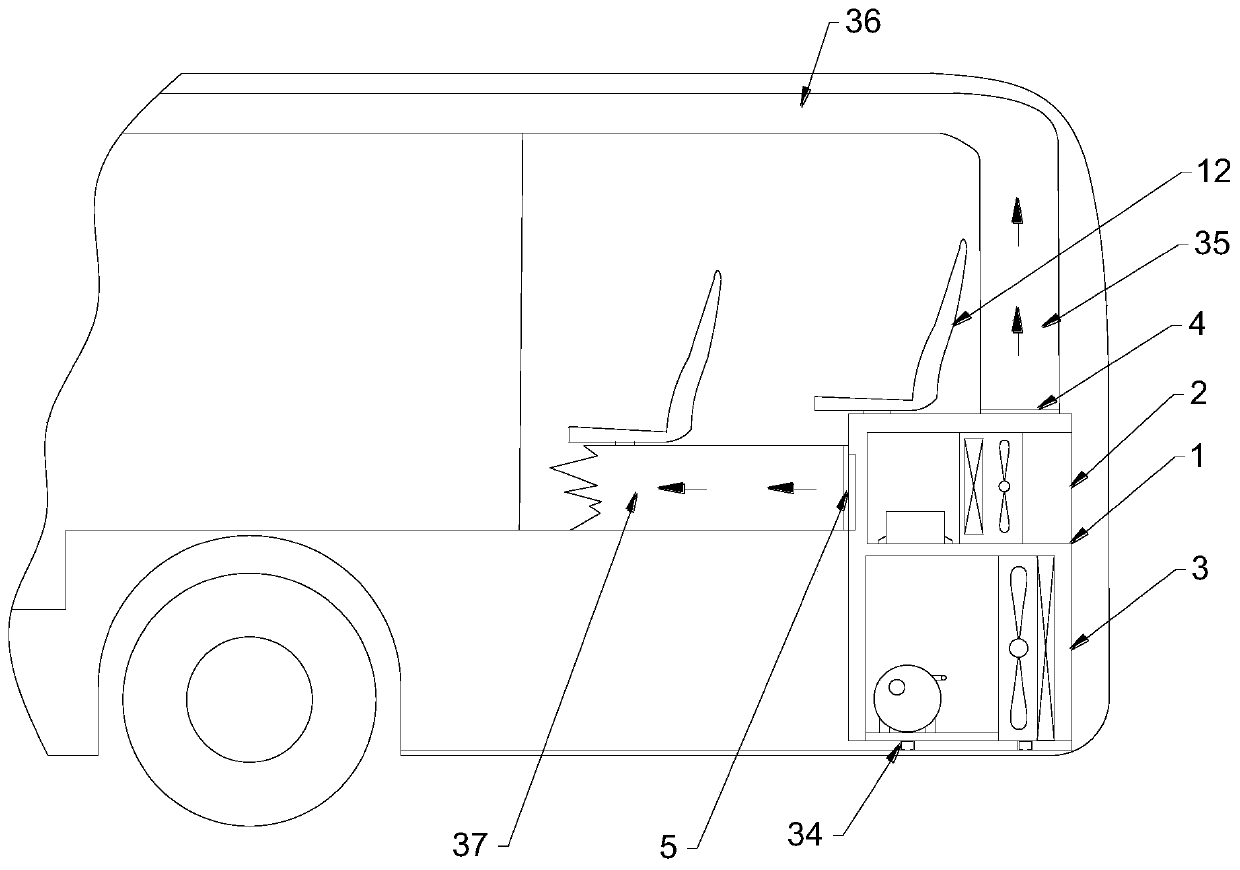
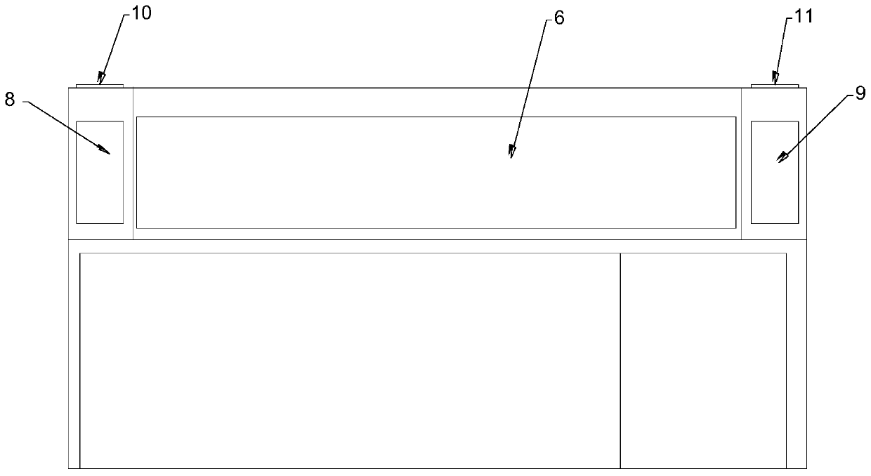
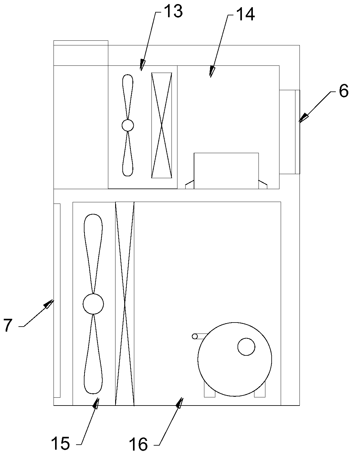
[0039] see in conjunction Figure 1 to Figure 6 As shown, an air conditioner for a passenger car includes: a frame structure 1 built in the trunk of the passenger car; the frame structure 1 is used to install the main body of the air conditioner for the passenger car.

[0040] The trunk of a passenger car is the cabin in the lower half of the rear of the passenger car. It is located from the bottom of the rear window of the passenger car to the floor of the car, and can extend forward to the rear wall of the car or under the seat of the vehicle.

[0041] The passenger car air conditioner provided by the embodiment of the present invention adopts a modular structure, the overall height of the vehicle remains unchanged after installation, forms a unified whole with the passenger car, has a compact structure, does not affect the space inside the car, improves the space utilization rate, and is convenient for installation and maintenance. Effectively reduce the weight of the passe...


PUM


Abstract

The invention provides a built-in air conditioner of a passenger vehicle. The built-in air conditioner comprises a frame structure (1), and the frame structure (1) is arranged in a trunk of the passenger vehicle; the frame structure (1) comprises an upper-layer structure (2) and a lower-layer structure (3); the upper-layer structure (2) is provided with air outlets and an air return port (6) whichface the interior of a carriage, the air outlets are used for feeding air to the interior of the carriage, and the air return port (6) is used for sucking air in the carriage; the lower-layer structure (3) is provided with cooling ports (7) facing the outside of a vehicle body. According to the air conditioner of the passenger vehicle, the modularized structure is adopted and is compact, the weight of the air conditioner of the passenger vehicle and the weight of the finished vehicle are effectively reduced, and the style development of the finished passenger vehicle is facilitated. The air conditioner is arranged in the tail box of the passenger vehicle, a rear window of the passenger vehicle is not shielded, and lighting of the carriage of the passenger vehicle is not influenced; through the built-in design, the probability of entry of impurities can be lowered, and the fault rate is reduced.

Description

technical field [0001] The invention belongs to the technical field of vehicle air conditioners, and in particular relates to a passenger car air conditioner. Background technique [0002] Air conditioners for passenger cars in the prior art are mainly top-mounted or back-mounted. [0003] The roof-mounted air conditioner is installed on the roof of the bus. The condensate return air and the air outlet are located on the roof. Rainy and snowy days are likely to affect the work of the external fan, and it is easy to enter debris and cause failure. Since the air outlet of the evaporator is located at the top of the interior compartment, the hot air is not easy to blow downwards, and in winter, the upper part of the compartment is hot and the lower part is cold, and the heating effect is poor. Moreover, the overhead air conditioner protrudes from the roof after installation, increases the height of the vehicle, increases the driving wind resistance, and also affects the exteri...

Claims


Application Information

Patent Timeline
Patent Type & Authority Applications(China)
IPC IPC(8): B60H1/00
Inventor 谭锋沈军罗宏斌李辉
Owner GREE ELECTRIC APPLIANCES INC
Learn More