Rotor position detection and initial position calibration method of permanent magnet synchronous motor

A technology of rotor position detection and permanent magnet synchronous motor, which is applied to the control of generators, motor generators, and electromechanical transmissions, etc., and can solve problems such as limitations

Active Publication Date: 2020-11-10
INST OF ELECTRICAL ENG CHINESE ACAD OF SCI
View PDF6 Cites 0 Cited by
  • Summary
  • Abstract
  • Description
  • Claims
  • Application Information

AI Technical Summary

Problems solved by technology

However, the methods proposed by the above two inventions require the encoder to have both UVW rough positioning and ABZ precise positioning functions. In fact, the encoder targeted is a hybrid encoder, not an incremental encoder in the true sense. ;In addition, in order to achieve zero calibration, the servo driver needs to control the motor to run at a certain speed in open loop, so it is necessary to prepare a special open loop control program and provide a strong current for the drive controller. The above special requirements limit the application of this type of method scene

Method used


Image

  • Rotor position detection and initial position calibration method of permanent magnet synchronous motor
  • Rotor position detection and initial position calibration method of permanent magnet synchronous motor
  • Rotor position detection and initial position calibration method of permanent magnet synchronous motor

Examples


Embodiment Construction

[0043] The present invention will be further described below in conjunction with the accompanying drawings and specific embodiments.

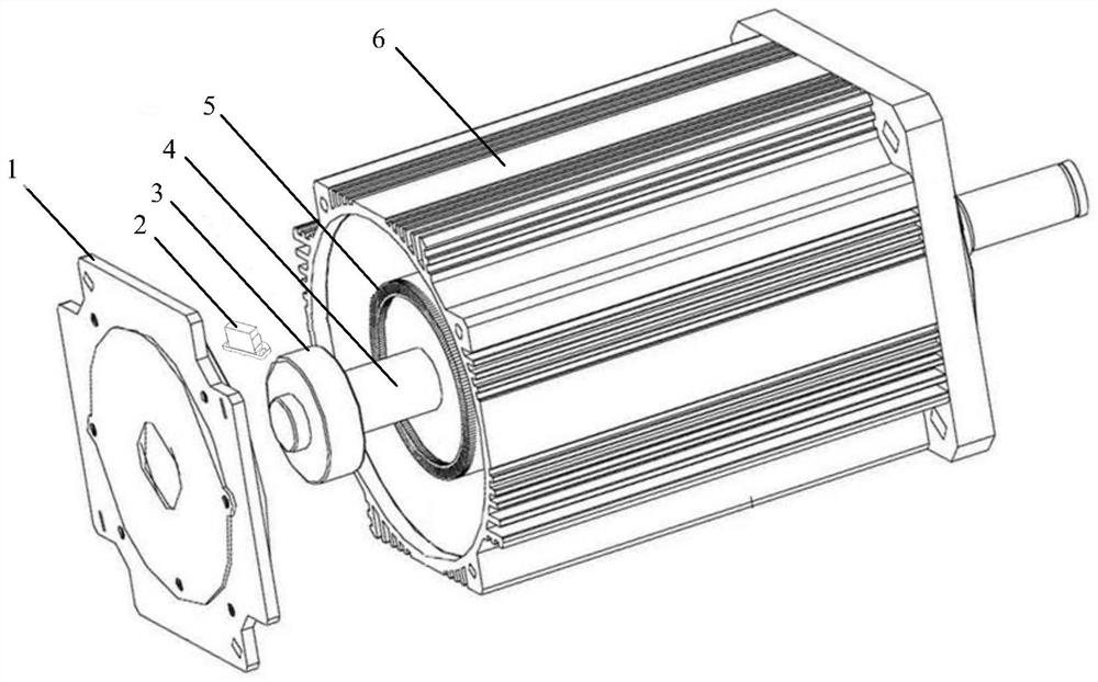
[0044] figure 1 It is the diagram of the structure of the incremental gear encoder and the installation relationship with the permanent magnet synchronous motor. The incremental gear encoder is composed of an induction head 2 and an encoder induction gear 3. The encoder induction gear 3 is installed on the permanent magnet synchronous motor shaft 4 and rotates synchronously with the permanent magnet motor shaft 4 and the motor rotor 5. The induction head 2 of the sensor is installed on the rear end cover 1 of the motor and maintains a fixed relative position with the stator 6 of the motor in space.

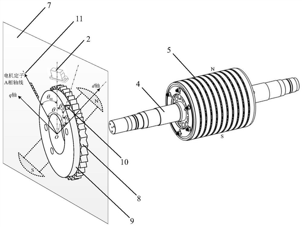
[0045] figure 2 It is a schematic diagram of the absolute position detection principle of the permanent magnet motor rotor of the present invention. The rotor 5 and stator 6 of the permanent magnet motor are projected onto the plane 7 where the...


PUM


Abstract

Provided is a PMSM rotor position detection and initial position calibration method. When a PMSM encoder induction gear rotates with a motor rotor, an induction head provided with a magnetic inductionchip detects the rotated angle of a motor rotor shaft, a path of A signals, a path of B signals and a path of Z signals are output, and based on processing of the signals, a motor rotor position angle theta is decomposed into an rotor initial position angle theta0 and an increment position angle thetaDelta. A high-speed AD sampling circuit divides a spatial position between two counting pulses finely, the quantification error of the position angle caused by integer pulse calculation is reduced, and the increment position angle thetaDelta of the motor rotor is calculated in high precision; andan estimated value of the position initial angle theta0 of the motor rotor is set as 0, an oscilloscope reads the phase difference between the motor rotor position angle theta and two paths of analogsignals uBC, and the position initial angle theta0 of the motor rotor can be calibrated after calculation.

Description

technical field [0001] The invention relates to a method for detecting the rotor position of a permanent magnet synchronous motor drive system. Background technique [0002] The high-performance permanent magnet synchronous motor drive system usually adopts vector control. In order to realize the independent closed-loop control of motor flux and torque, it is necessary to decouple the excitation component and torque component of the motor stator current, and the absolute position of the permanent magnet synchronous motor rotor The detection of is a necessary condition to realize the stator current decoupling control. In the prior art, an encoder installed on the motor is generally used to obtain the position information of the motor. In order to obtain the absolute position of the motor rotor, the most common solution is to use an absolute encoder, but due to its complex internal structure and high cost, the application of absolute encoders is greatly limited. As an altern...

Claims


Application Information

Patent Timeline
Patent Type & Authority Patents(China)
IPC IPC(8): H02P21/18H02P21/32
Inventor 张剑颜朝鹏彭萌李文善温旭辉
Owner INST OF ELECTRICAL ENG CHINESE ACAD OF SCI
Why Eureka
Try Eureka