Permanent magnet synchronous motor maximum efficiency torque ratio control method and permanent magnet synchronous motor maximum efficiency torque ratio controller

A technology of permanent magnet synchronous motor and maximum efficiency, which is applied in the direction of motor generator control, electromechanical brake control, electronic commutation motor control, etc. Slow and so on

Active Publication Date: 2019-05-31
HUNAN UNIV
View PDF4 Cites 3 Cited by
  • Summary
  • Abstract
  • Description
  • Claims
  • Application Information

AI Technical Summary

Problems solved by technology

Rotor field oriented vector control is a control strategy with optimal torque dynamic response. The drive motor using vector control has high operating efficiency near the rated speed, but the efficiency far away from the rated speed area is not high.
Therefore, in order to improve the operating efficiency of the motor, control methods such as minimum loss control have been proposed, but the dynamic response of minimum loss control is difficult to meet the requirements of frequent start-stop and

Method used


Image

  • Permanent magnet synchronous motor maximum efficiency torque ratio control method and permanent magnet synchronous motor maximum efficiency torque ratio controller
  • Permanent magnet synchronous motor maximum efficiency torque ratio control method and permanent magnet synchronous motor maximum efficiency torque ratio controller
  • Permanent magnet synchronous motor maximum efficiency torque ratio control method and permanent magnet synchronous motor maximum efficiency torque ratio controller

Examples


Embodiment Construction

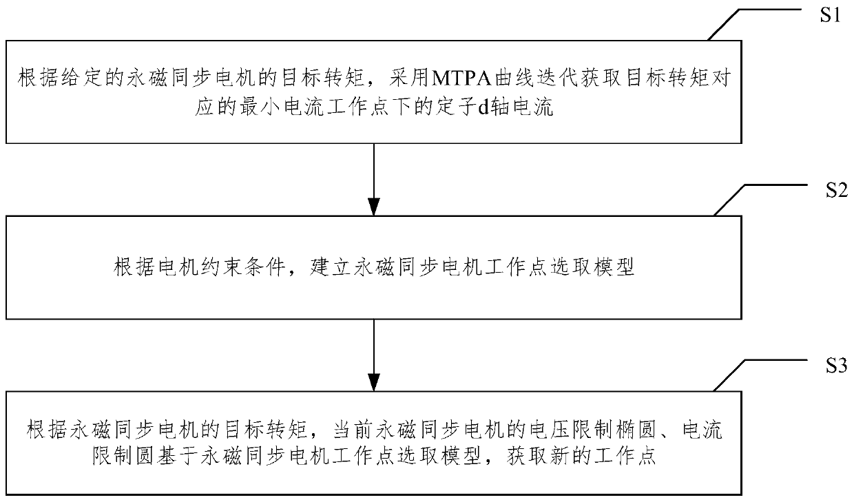
[0083] In order to better explain the present invention and facilitate understanding, the present invention will be described in detail below through specific embodiments.

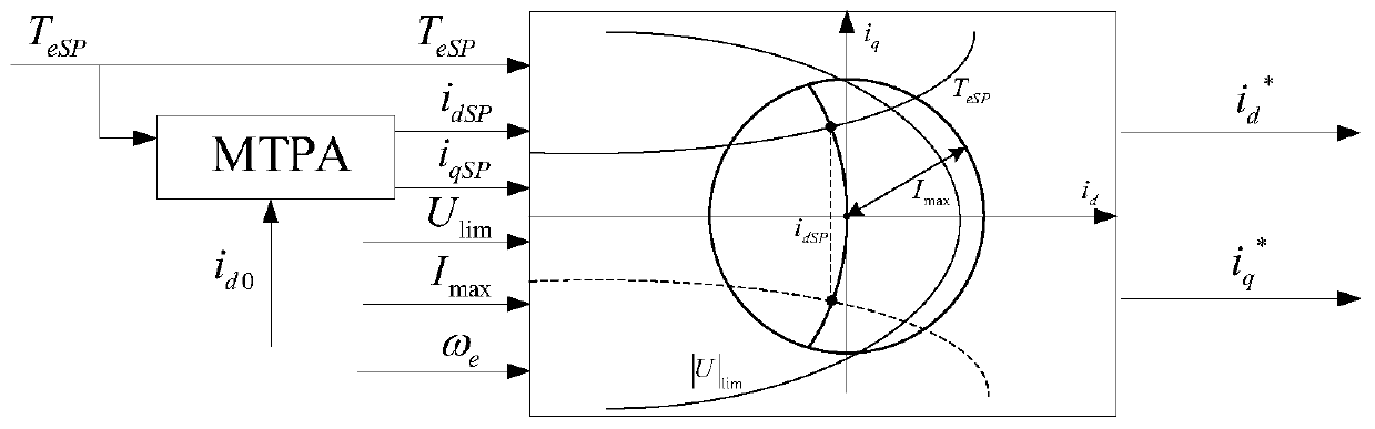
[0084] The maximum efficiency torque ratio control structure diagram of the present invention is as follows figure 2 shown. Its basic control rules are as follows:

[0085] (1) Select the current set {(i d ,i q )}, under the premise of satisfying the constraints, the actual torque T e As close as possible to the target torque T eSP ,which is:

[0086] {(i d ,i q )}=argmin|T eSP -T e | (1)

[0087] and satisfy the constraints:

[0088]

[0089] Among them: |U|, |I|-stator voltage and current single-phase amplitude; u d , u q - stator d-axis voltage and q-axis voltage; i d , i q -Stator d-axis current and q-axis current; where the 3 / 2 transformation adopts the amplitude-invariant constraint.

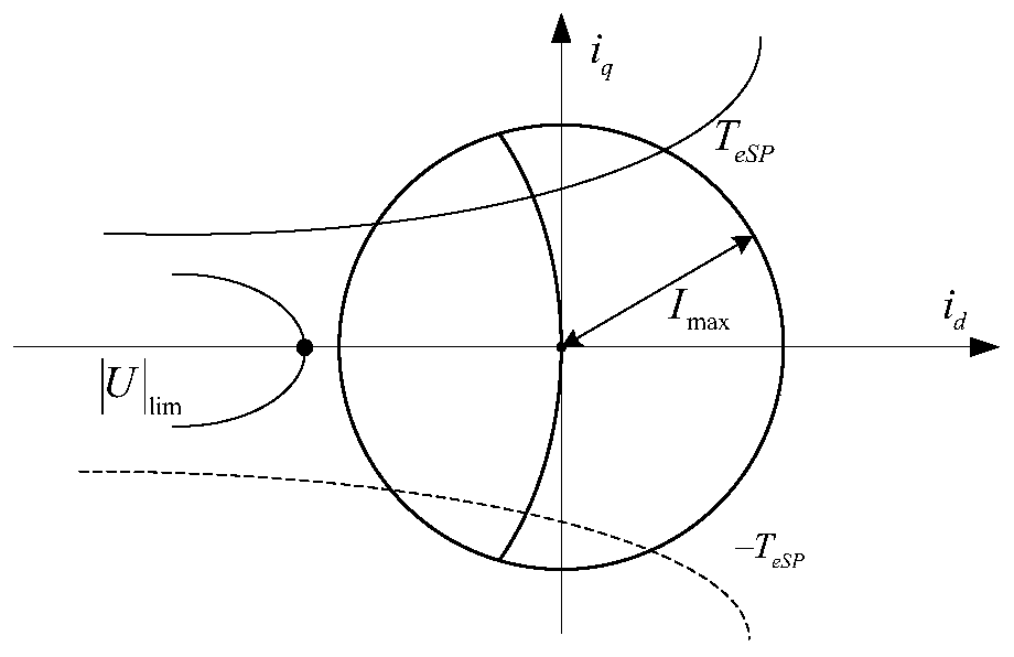
[0090] (2) In the collection {(i d ,i q )} to select the combination closest to the MTPA curve...


PUM


Abstract

The invention relates to a permanent magnet synchronous motor maximum efficiency torque ratio control method and permanent magnet synchronous motor maximum efficiency torque ratio controller. The method comprises steps of S1, according to the given target torque of the permanent magnet synchronous motor, using an MTPA curve to iteratively obtain the stator d-axis current under the minimum currentoperating point corresponding to the target torque; S2, according to a motor constraint condition, establishing a permanent magnet synchronous motor operating point selection model; and S3, accordingto the target torque of the permanent magnet synchronous motor, the current voltage limiting ellipse and current limiting circle of the permanent magnet synchronous motor, obtaining a new operating point based on the permanent magnet synchronous motor operating point selection model. Compared with a linearization method, the method greatly weakens the voltage constraint condition and obtains better dynamic response, can accurately obtain the intersection of the MTPA curve and the current limiting curve or voltage limiting curve to avoid torque instability or even oscillation caused by a calculation error.

Description

technical field [0001] The invention relates to a permanent magnet synchronous motor control technology, in particular to a method for controlling the maximum efficiency torque ratio of a permanent magnet synchronous motor and a controller. Background technique [0002] The permanent magnet synchronous motor has become the most competitive electric vehicle traction motor due to its small size, high efficiency, and high power density. It has been widely used in electric vehicles in Japan. The closed-loop permanent magnet synchronous motor The speed control system can achieve excellent dynamic performance, high precision and wide adjustment range, and has a good application prospect in occasions requiring high performance and fast response. Therefore, the performance of the motor will determine the performance of the electric vehicle to a large extent. Permanent magnet synchronous motor has high power density, high efficiency and excellent speed regulation performance, so it ...

Claims


Application Information

Patent Timeline
IPC IPC(8): H02P21/22H02P21/05
Inventor 刘平黄守道陈常乐王建武覃思雨李力争
Owner HUNAN UNIV
Why Eureka
Try Eureka