Road surface cutting equipment and method for road construction

A cutting equipment and road surface technology, which is applied in the direction of roads, roads, road repairs, etc., can solve the problems of large diameter cutting blades, cutting and cleaning at the corners of difficult road surface depressions, and the guide wheels can not leave cutting marks, etc., so as to reduce vibration and Impact, reduction of consumables usage cost, and effect of simplifying equipment usage

Inactive Publication Date: 2019-06-04
郭二艳
View PDF6 Cites 3 Cited by
  • Summary
  • Abstract
  • Description
  • Claims
  • Application Information

AI Technical Summary

Problems solved by technology

[0006] Aiming at the technical problem in the prior art that it is difficult for the cutting saw blade to cut to the residual part at the corner, the present invention provides a road surface cutting equipment and method for road construction, which adopts a transmission mechanism that can be flexibly linked and separated from the cutting blade, The purpose of flexibly integrating the guide wheel with the pre-cutting equipment is achieved, and it is difficult to clean the corners of the road surface depression due to the large diameter of the cutting disc, and the guide wheel of the cutting disc cannot leave cutting marks in the pre-cutting direction technical issues

Method used


Image

  • Road surface cutting equipment and method for road construction
  • Road surface cutting equipment and method for road construction
  • Road surface cutting equipment and method for road construction

Examples


Embodiment 1

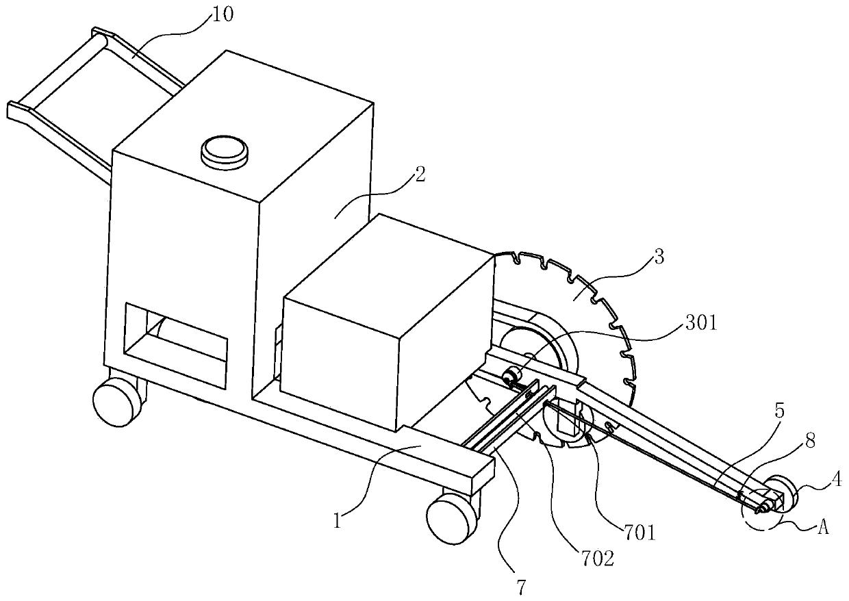
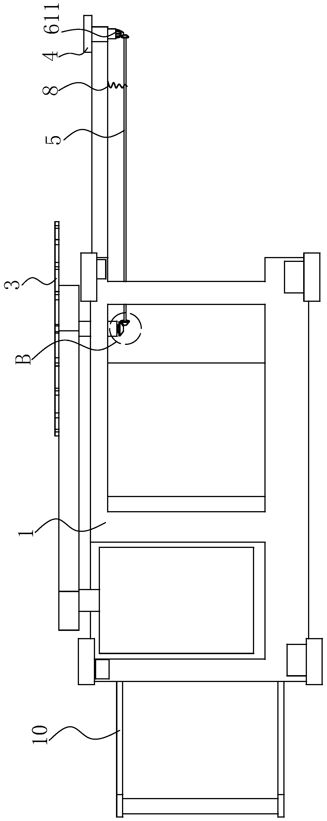
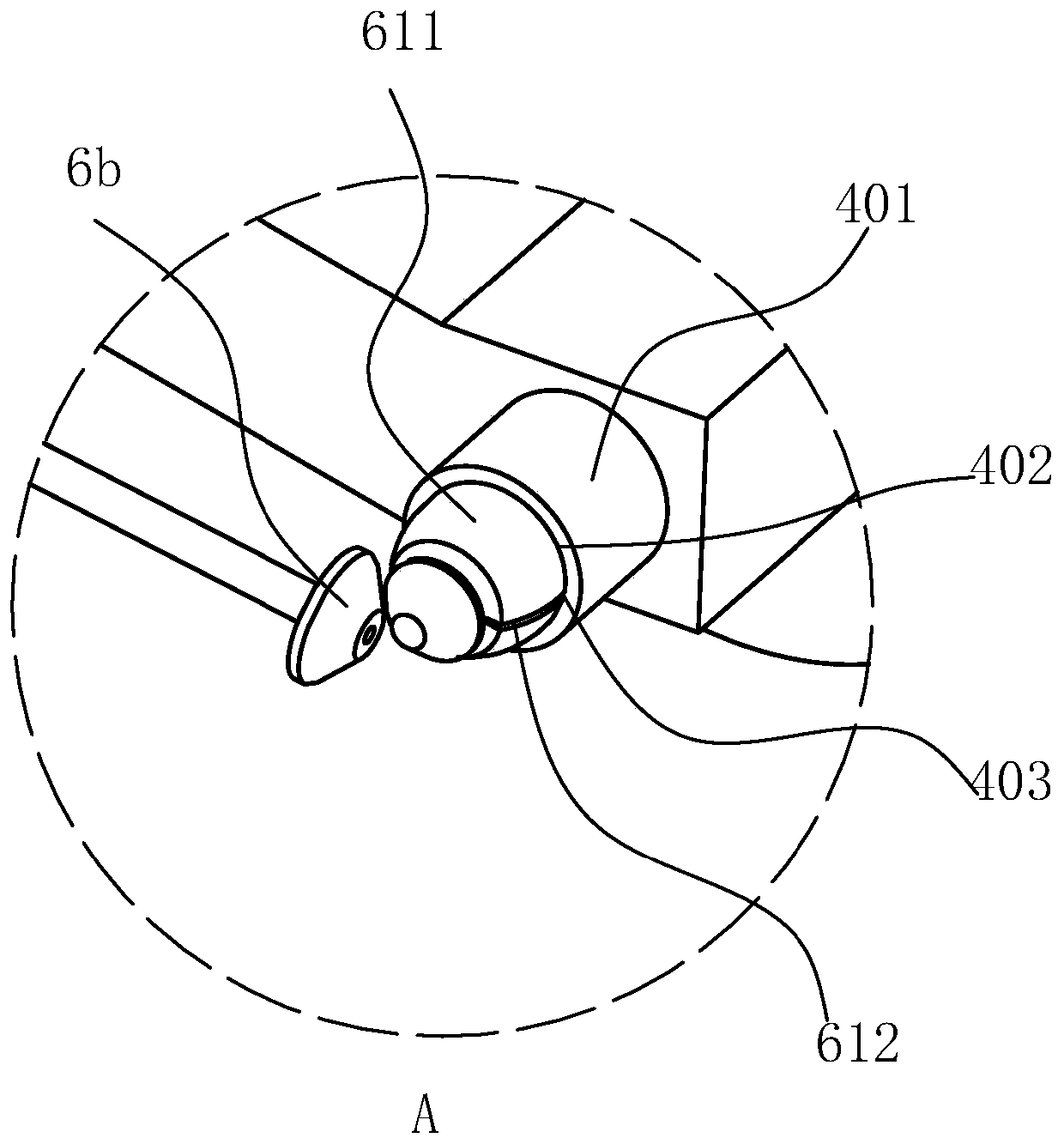
[0049] like Figure 1 to Figure 6 As shown, a road surface cutting equipment for road construction includes a frame body 1, a driving machine 2 and a cutting blade 3 driven by the driving machine 2 are installed on the frame body 1, and guide wheels are installed on the front part of the frame body 1 4. The guide wheel 4 is coplanar with the cutting blade 3, and the guide wheel 4 and the cutting blade 3 are respectively supported by the guide shaft 401 and the saw blade shaft 301 that are movably installed on the frame body 1. The frame body 1 is provided with Connect the drive shaft 5 of the cutting piece 3 and the guide wheel 4, a tension spring 8 is arranged between the frame body 1 and the drive shaft 5, and the end of the drive shaft 5 close to the guide wheel 4 is always connected with the drive by the tension spring 8 The mechanism connection of the guide shaft 401 realizes the purpose of using only one set of driving equipment to control the power transmission process ...

Embodiment 2

[0061] like Figure 7 As shown, on the basis that the basic technical solution of Embodiment 1 remains unchanged, the spring groove 602 is arranged along the axial direction of the protruding part 601, and the groove bottom surface of the first groove 302 is provided with a The arc-shaped pit 304, using the arc-shaped pit 304 to increase the friction between the ball 9 and the first groove 302, prevent the ball 9 from completely eliminating the driving force between the two, and appropriately increase the protrusion of the saw blade shaft 301 Part 601 of the driving force.


PUM


Abstract

The invention relates to road surface cutting equipment and method for road construction, and belongs to the technical field of road surface construction equipment. The road surface cutting equipmentcomprises a frame body; a driving machine and a cutting blade driven by the driving machine are mounted on the frame body; a guide wheel is arranged at the front part of the frame body, the guide wheel and the cutting blade are coplanar, the guide wheel and the cutting blade are respectively and correspondingly supported by a guide shaft and a saw blade shaft which are movably arranged on the frame body; a transmission shaft for connecting the cutting blade and the guide wheel is arranged on the frame body, and two ends of the transmission shaft are respectively and correspondingly connected with the guide shaft and the saw blade shaft through a bevel gear transmission set; a supporting rod is arranged on the frame body, a strip-shaped hole is formed in the supporting rod, and the transmission shaft penetrates through the strip-shaped hole; a push rod is arranged in the supporting rod. A motor is adopted to drive the push rod to rotate, and the push rod is in threaded connection with asliding sleeve, so that the rotating push rod can push the sliding sleeve and the transmission shaft penetrating through the sliding sleeve to one side close to the cutting blade, the bevel gear transmission sets at two ends of the transmission shaft are correspondingly connected with the cutting blade and the guide wheel respectively, and power transmission is achieved.

Description

technical field [0001] The invention relates to the technical field of road construction equipment, in particular to a road surface cutting equipment and method for road construction. Background technique [0002] Pots or subsidences often appear on roads after many years of use. The causes of pits or subsidences include subgrade settlement and vehicle rolling. When repairing the above-mentioned defects, it is necessary to clean up the defective road sections before pouring New concrete or asphalt mixture, to prevent the poured mixture from being unevenly connected to the original road surface, or not firmly bonded to each other. If the cleaning is not thorough, there will be a lot of waste residue at the bottom of the road pit, and it is difficult for the newly poured structure to be in contact with the bottom of the road pit. The surface of the concrete is effectively combined, and the pouring layer is shallow, and it is easy to be rolled out by vehicles, and it is also ea...

Claims


Application Information

Patent Timeline
Patent Type & Authority Applications(China)
IPC IPC(8): E01C23/09
Inventor 郭二艳富平洋朱江霞孔祥一段志超冯志超贾驰李岩王健康关志杰
Owner 郭二艳
Why Eureka
Try Eureka