Intelligent water conservancy drilling machine

A drilling machine and water conservancy technology, applied in drilling equipment and methods, drilling equipment, earthwork drilling, etc., can solve the problem of hydraulic system automatically adjusting the height of the workbench, affecting the drilling accuracy, and inconvenient and quick switching of different types of drill bits, etc. question

Inactive Publication Date: 2019-06-04
巩浩
View PDF0 Cites 0 Cited by
  • Summary
  • Abstract
  • Description
  • Claims
  • Application Information

AI Technical Summary

Problems solved by technology

[0003] 1. The existing technology does not use the hydraulic system to automatically adjust the height of the workbench. When it is necessary to perform high-level drilling on the dam, the existing technology is difficult to control the movement of the workbench, thereby affecting the drilling accuracy;
[0004] 2. The prior art does not have a toolbox for classifying and placing different types of drill bits. When it is necessary to drill holes in power generation tunnels, water diversion channels, etc., the size and position of the holes must be controlled to ensure the safety and stability of the entire water conservancy project. It is necessary to select different types of drill bits for drilling according to the needs (for example: the diameter of the cable, the thickness of the rope, and the size of the pipe). The existing technology cannot conveniently and quickly switch between different types of drill bits;
[0005] 3. The existing technology does not have a scale line for measuring the depth of the borehole. When it is necessary to drive piles on the dam, the depth of the borehole needs to be controlled. The existing technology lacks the function of measuring the depth of the hole in real time, thereby affecting the efficiency of the entire water conservancy project , progress and security stability

Method used


Image

  • Intelligent water conservancy drilling machine
  • Intelligent water conservancy drilling machine
  • Intelligent water conservancy drilling machine

Examples


Embodiment Construction

[0018] In order to make the technical means, creative features, goals and effects achieved by the present invention easy to understand, the present invention will be further described below in conjunction with specific embodiments.

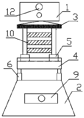
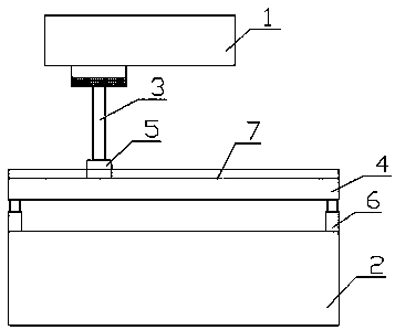
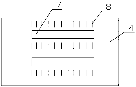
[0019] Such as Figure 1 to Figure 4 As shown, a kind of intelligent water conservancy drilling machine includes drilling machine book 1, base 2, support frame 3, support plate 4, slider 5 and telescopic rod 6, and described drilling machine body 1 is fixedly connected on the described On the support frame 3, the slider 5 is fixedly connected to the bottom of the support frame 3, and the top of the support plate 4 is provided with two chute 7, and the sliding fast 5 is slidably connected to the chute 7 Inside, the bottom four corners of the support plate 4 are fixedly connected with the telescopic rod 6, the bottom of the telescopic rod 6 is fixedly connected with the top four corners of the base 2, and the two sides of the chute 7 There is a sca...


PUM


Abstract

The invention discloses an intelligent water conservancy drilling machine, and relates to the field of water conservancy engineering. The drilling machine includes a drilling machine body, a pedestal,a support frame, a supporting plate, slide blocks and telescoping rods; the drilling machine body is fixedly connected to the support frame; the slide blocks are fixedly connected to the bottom of the support frame; the top of the supporting plate is provided with two slide grooves; the slide blocks are slidingly connected to the slide grooves; each of the four corners at the bottom of the supporting plate is fixedly connected to one telescoping rod; the bottom of each telescoping rod is fixedly connected to each of the four corners on the top of the pedestal; and the two sides of each slidegroove are provided with graduation lines. The drilling machine body is fixed on the support frame and slides in the slide groove with the slide blocks, so that punching feed movement can be realized;the telescoping rods can realize the up and down moving of the supporting plate through a hydraulic system; and operators can conveniently grasp the depth of punching through the graduation lines.

Description

technical field [0001] The invention relates to the field of hydraulic engineering, in particular to an intelligent hydraulic drilling machine. Background technique [0002] Drilling machines are widely used in the field of water conservancy engineering. At present, the existing drilling technology largely meets the requirements of drilling accuracy and quality in water conservancy engineering. However, at the same time, the existing drilling machine technology Also there are following shortcoming and weak points: [0003] 1. The existing technology does not use the hydraulic system to automatically adjust the height of the workbench. When high-level drilling is required on the dam, the existing technology is difficult to control the movement of the workbench, thereby affecting the drilling accuracy; [0004] 2. The prior art does not have a toolbox for classifying and placing different types of drill bits. When it is necessary to drill holes in power generation tunnels, wa...

Claims


Application Information

Patent Timeline
IPC IPC(8): E21B7/00E21B15/00E21B47/04E21B41/00
Inventor 巩浩
Owner 巩浩
Why Eureka
Try Eureka