Method for enhancing salt cavern storage utilization rates by utilizing connected wells to discharge brine from bottom of cavity

A technology for connecting wells and utilization rates, which is applied in earth-moving drilling, wellbore/well components, and production fluids. and other problems, to achieve the effect of improving the utilization rate of the dissolution cavity and increasing the volume of the storage tank

Active Publication Date: 2019-06-04
江苏苏盐井神股份有限公司 +1
View PDF5 Cites 7 Cited by
  • Summary
  • Abstract
  • Description
  • Claims
  • Application Information

AI Technical Summary

Problems solved by technology

The traditional single well gas injection (or oil injection) brine removal scheme cannot use the pores between solid particles to store natural gas or oil
[0004] In summary, the traditional single-well gas injection (or oil injection) brine removal scheme will not only

Method used


Image

  • Method for enhancing salt cavern storage utilization rates by utilizing connected wells to discharge brine from bottom of cavity
  • Method for enhancing salt cavern storage utilization rates by utilizing connected wells to discharge brine from bottom of cavity
  • Method for enhancing salt cavern storage utilization rates by utilizing connected wells to discharge brine from bottom of cavity

Examples


Embodiment 1

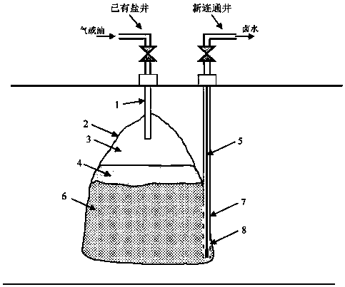
[0043] (1) In the well mine salt mine area, the volume of A salt well is 250,000 m 3 , the shape and tightness of the salt well dissolution cavity meet the technical requirements of the salt cavern gas storage, and the injection and production strings already exist in the salt well.

[0044] (2) Using sonar cavity measurement technology, the cavity top position of Well A's dissolution cavity has been determined to be -1050m, and the cavity bottom position is -1110m.

[0045] (3) A new well A' is drilled at a distance of 50m from the wellhead of Well A. The bottom of Well A' is connected to the deepest part of the dissolution cavity of Well A, and the two salt wells A and A' form a connected well. Casing and cementing are run in well A', and screen holes are set in the lower part of the casing to establish hydraulic connection between A' and well A's solution cavity. The electric submersible pump and the corresponding brine discharge pipe are lowered into the well A', and the ...

Embodiment 2

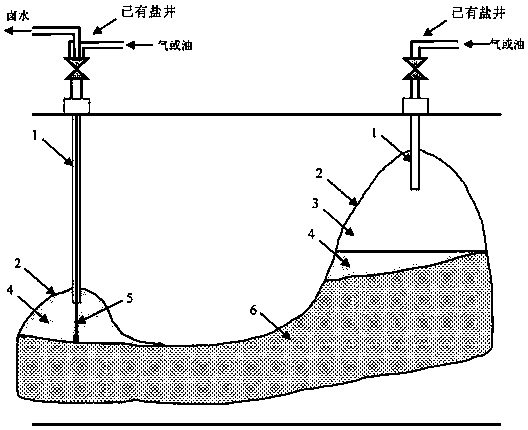
[0050] (1) In the Jingkuang salt mine area, two salt wells A and B form a group of connected wells, and the total volume of the two salt wells is 300,000 m 3 , the shape and tightness of the salt well dissolution cavity meet the technical requirements of the salt cavern gas storage, and the injection and production strings already exist in the salt well.

[0051] (2) Using sonar cavity measurement technology, the top position of the dissolved cavity of Well A is -1085m, the position of the bottom of the cavity is -1100m, the position of the top position of the dissolved cavity of Well B is -1050m, and the position of the bottom of the cavity is -1090m.

[0052] (3) Well A is selected as a "brine discharge well", and an electric submersible pump and corresponding brine discharge pipes are lowered into its injection-production string.

[0053] (4) Through the electric submersible pump, the brine in the dissolved cavity is discharged from Well A to the ground; at the same time, n...

Embodiment 3

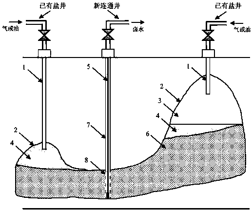
[0057] (1) In the Jingkuang salt mine area, two salt wells A and B form a group of connected wells, and the total volume of the two salt wells is 450,000 m 3 , The shape and tightness of the salt well dissolution cavity meet the technical requirements of the salt cavern oil storage depot, and the injection-production string has already been installed in the salt well.

[0058] (2) Using sonar cavity measurement technology, the top position of the dissolved cavity of Well A is -1040m, the position of the bottom of the cavity is -1090m, the position of the top of the dissolved cavity of Well B is -1085m, and the position of the bottom of the cavity is -1100m.

[0059] (3) Drill a new connecting well B' at a distance of 70m from the wellhead of Well B, and the bottom of Well B' is connected to the deepest part of the existing dissolution cavity. Run the casing in the B' well and cement the well, and set up screen holes in the lower part of the casing to establish a hydraulic conn...


PUM


Abstract

The invention relates to a method for enhancing salt cavern storage utilization rates by utilizing connected wells to discharge brine from the bottom of a cavity. The method is to place an electric submersible pump and other underground equipment through existing salt wells or new salt wells during the gas injection or oil injection and brine discharging of salt cavern storages, so that the brineat the bottom of a cavity can be discharged. The method can be applied to the gas injection or oil injection and brine discharging of various salt cavern storages, especially suitable for the gas injection or oil injection and brine discharging of well and rock salt connected well sets; and the method can increase the effective volumes of salt caverns to store gas or oil, and therefore, the cavityutilization rates of the salt cavern storages can be enhanced.

Description

technical field [0001] The invention relates to a method for improving the utilization rate of a salt cavern storage by utilizing a communication well to discharge brine from the bottom of a cavity, and belongs to the construction field of a salt cavern storage (gas storage or oil storage). Specifically, during the brine discharge process of gas injection (or oil injection) in the salt cavern storage, downhole equipment such as electric submersible pumps are installed through existing salt wells or new salt wells to fully discharge the brine in the dissolution cavity and increase the capacity of the salt cavern storage. Effective volume, thereby improving the utilization rate of the solution cavity of the salt cavern storage. The invention can be applied to gas injection (or oil injection) for brine discharge in various types of salt cavern storages, and is especially suitable for well groups connected with mines and salts. Background technique [0002] At present, the conv...

Claims


Application Information

Patent Timeline
IPC IPC(8): E21F17/16E21B43/00
Inventor 刘凯刘正友张文广
Owner 江苏苏盐井神股份有限公司
Why Eureka
Try Eureka