
Steam trap leakage-proof improvement method and steam pipeline drainage device

A drainage device and steam trap technology, applied in steam traps, mechanical equipment, etc., can solve the problems of reducing pipeline pressure, steam leakage, steam leakage, etc., achieve the effects of reducing leakage, solving steam leakage, and low manufacturing cost

Pending Publication Date: 2019-06-04
GUODIAN LONGYUAN POWER TECH ENG
View PDF0 Cites 0 Cited by
  • Summary
  • Abstract
  • Description
  • Claims
  • Application Information

AI Technical Summary

Problems solved by technology

The steam trap of the existing steam pipeline drainage device often has a lot of steam entering during normal use, which will cause part of the steam to leak, reduce the pipeline pressure, and cause steam leakage.

Method used


Image

  • Steam trap leakage-proof improvement method and steam pipeline drainage device
  • Steam trap leakage-proof improvement method and steam pipeline drainage device

Examples


Embodiment Construction

[0023] The present invention will be described in detail below with reference to the accompanying drawings and examples. Each example is provided by way of explanation of the invention, not limitation of the invention. In fact, those skilled in the art will recognize that modifications and variations can be made in the present invention without departing from the scope or spirit of the invention. For example, features illustrated or described as part of one embodiment can be used on another embodiment to yield a still further embodiment. Therefore, it is intended that the present invention includes such modifications and variations as come within the scope of the appended claims and their equivalents.

[0024] In the description of the present invention, the terms "longitudinal", "transverse", "upper", "lower", "front", "rear", "left", "right", "vertical", "horizontal", " The orientations or positional relationships indicated by "top", "bottom", etc. are based on the orienta...


PUM


Abstract

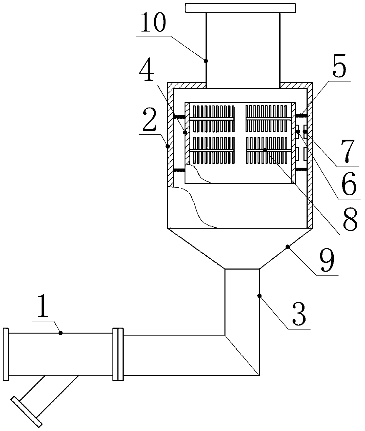
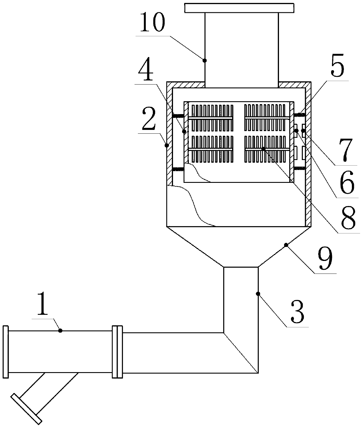
The invention relates to the technical field of steam delivery pipeline hydrophobic equipment, in particular to a steam trap leakage-proof improvement method and a steam pipeline drainage device. Thesteam trap leakage-proof improvement method is characterized in that a liquid storage device used for liquid temporary storage is arranged in front of an inlet of a steam trap, and the liquid flowingin a steam pipeline firstly enters the liquid storage device to receive preliminary gas-liquid separation; and the liquid storage device is connected with the inlet of the steam trap, and the liquid subjected to preliminary gas-liquid separation enters the steam trap for liquid discharge. The steam pipeline drainage device comprises the steam trap, the steam trap comprises a valve body, the valvebody is provided with the valve body inlet and a valve body outlet, and the liquid storage device used for liquid temporary storage is connected with the valve body inlet. The steam trap leakage-proofimprovement method and the steam pipeline drainage device solve the problem of steam leakage in a traditional steam trap, and also have the advantages of being simple and compact in structure, low inmanufacturing cost, simple and convenient to use and the like.

Description

technical field [0001] The present invention relates to the technical field of drainage equipment for steam delivery pipelines, and more specifically, to a method for improving steam leakage prevention of steam traps and a drainage device for steam pipelines. Background technique [0002] The function of the steam trap (referred to as the steam trap) is to automatically remove the steam condensed water in the heating equipment or the steam pipeline, and at the same time, it can also ensure that the steam does not leak. Because the steam trap has the function of blocking steam and draining water, it can make the steam heating equipment evenly heat, so that the latent heat contained in the steam can be fully utilized. [0003] The action objects of the steam trap are liquid and gas respectively, and it has the function of draining water and stopping the flow of gas, and its main function is to realize the separation of gas and liquid. The steam trap of the existing steam pipe...

Claims


Application Information

Patent Timeline
IPC IPC(8): F16T1/00F16T1/38
Inventor 董浩
Owner GUODIAN LONGYUAN POWER TECH ENG
Learn More